Problem FAULTY Silent Scope EX

Marlow007

Newbie
Credits
9CR
Hi All,

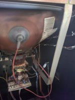
I have a problem with my silent Scope EX machine, it's been all working perfect and I was playing it and the screen went off, but the dot matrix was still on but no screen. Turned off the machine and turned it back on and nothing at all is coming on visually on the machine.

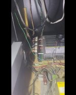
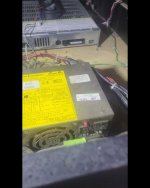
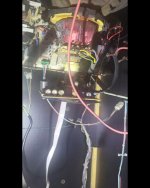
I have attached an image of the machine and will see if I can up load a video if it allows me to.

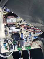
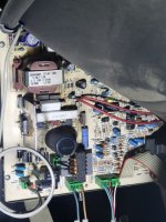
I'm getting a flashing green and red light from the Board behind the CRT, and a static electrical type sound in sequence with the red and green lights coming on and off


20230606_103414.jpg20230606_103847.jpg
20230606_103849.jpg

Thanks everyone for your time really appreciated Craig
 

Attachments

  • 20230606_103407.jpg
    20230606_103407.jpg
    105 KB · Views: 8
  • 20230606_103845.jpg
    20230606_103845.jpg
    106.5 KB · Views: 3
  • 20230606_103848.jpg
    20230606_103848.jpg
    106 KB · Views: 10

tb2000

Active member
Feedback
4 (100%)
Credits
3,219CR
It's an Intervideo 21" dual sync monitor. It sounds like you might be getting HV, but maybe no crt neck heater voltage. Can you see an orange glow coming from the neck of the crt after powering it up?
 

Marlow007

Newbie
Credits
9CR
It's an Intervideo 21" dual sync monitor. It sounds like you might be getting HV, but maybe no crt neck heater voltage. Can you see an orange glow coming from the neck of the crt after powering it up?
Hi There,
First of all thanks for your Time to message, I believe it is a intervideo and I'm getting no glow from the neck at all. Would this also effect the dot matrix as everything powers on but nothing seems to come on.

I here a electrical noise, like something is trying to work but nothing.

I have attached some images below.

Thanks Again Craig
 

Attachments

  • 20230606_115335.jpg
    20230606_115335.jpg
    54.7 KB · Views: 12
  • Screenshot_20230607_201218_Gallery.jpg
    Screenshot_20230607_201218_Gallery.jpg
    67.2 KB · Views: 13
  • Screenshot_20230607_201221_Gallery.jpg
    Screenshot_20230607_201221_Gallery.jpg
    58.8 KB · Views: 13
  • Screenshot_20230607_201225_Gallery.jpg
    Screenshot_20230607_201225_Gallery.jpg
    66.8 KB · Views: 12

Marlow007

Newbie
Credits
9CR
Looking into this it looks like it may be the game board as I'm getting no sound or power to the dot matrix, I'm totally lostbwith it at the moment all the lights come on internally, power pack, dot matrix power and the gameboard but nothing at all on both screen or sound.

Any ideas anyone and thanks for taking the time to look
Craig
 

lix

Active member
vacBacker
Feedback
1 (100%)
Credits
545CR
Game board is based on Konami Viper hardware which are problematic to say the least. If you’re not getting any video from the board, no errors, no demo sound or coining up and going into the game, and you’ve checked that all power line voltages on the jamma harness going into the pcb are correct then yes, it’s most likely the game board has failed.

I have three Thrill Drive 2 boards and they have all failed with dead CPUs, a reflow gave one board an extra week of life before it finally kicked the bucket.

I’ve seen a few of these SS-Ex cabs with corrupt graphics recently so I’m guessing their time is due now. Sorry to be the bearer of bad news. Someone might still have a working board out there though.
 

ArcadePCB

User
vacBacker
Credits
509CR
I don't know this game board, but what about the classic approach? Checking voltages on the game board, checking the clock signal and the reset signal at the CPU, testing bus signals, etc.
'It may be the game board' will not help finding out it is or not. What are the tools you have access to? Multimeter, logic tester, oscilloscope, Fluke 9010A, ....? Do you have a schematic for this board?
 

Marlow007

Newbie
Credits
9CR
I don't know this game board, but what about the classic approach? Checking voltages on the game board, checking the clock signal and the reset signal at the CPU, testing bus signals, etc.
'It may be the game board' will not help finding out it is or not. What are the tools you have access to? Multimeter, logic tester, oscilloscope, Fluke 9010A, ....? Do you have a schematic for this board?
Hi pal,

Thanks for the reply I have a multi meter and the schematic for the board. I'm quite new to the Retro gaming boards. Would be great if I could find someone with more knowledge to take a look as I mentioned I new to this type of machine.

Thanks for the reply
 

ArcadePCB

User
vacBacker
Credits
509CR
Hi pal,

Thanks for the reply I have a multi meter and the schematic for the board. I'm quite new to the Retro gaming boards. Would be great if I could find someone with more knowledge to take a look as I mentioned I new to this type of machine.

Thanks for the reply
Yes, that's a good idea looking for help. I would recommend you to buy or build at least a logic tester so you can recognize toggling signals (e.g. clock, bus signals). Static signals can be tested using the multimeter, too.
What you can do yourself: Check the voltage at the opposite edge the power comes in on a 74xx integrated circuit. The side with the notch is pin 1 / pin 14 (16). Positive supply pin is pin 14 (16), negative supply pin is pin 7 (8). it should be 5V +/- 0.5V. If OK, take the schematics and look for the CPU. Search for the reset pin and test this pin to GND. Depending on the CPU, the pin should be 5V for a short time after powering up the device and then remain at 0V level or it should be 0V for a short time and then remain at 5V level. If there is a static signal during power up, the CPU won't start.
 

Marlow007

Newbie
Credits
9CR
Yes, that's a good idea looking for help. I would recommend you to buy or build at least a logic tester so you can recognize toggling signals (e.g. clock, bus signals). Static signals can be tested using the multimeter, too.
What you can do yourself: Check the voltage at the opposite edge the power comes in on a 74xx integrated circuit. The side with the notch is pin 1 / pin 14 (16). Positive supply pin is pin 14 (16), negative supply pin is pin 7 (8). it should be 5V +/- 0.5V. If OK, take the schematics and look for the CPU. Search for the reset pin and test this pin to GND. Depending on the CPU, the pin should be 5V for a short time after powering up the device and then remain at 0V level or it should be 0V for a short time and then remain at 5V level. If there is a static signal during power up, the CPU won't start.
Thank you so much for the advice, I will buy a logic tester and start from where you mentioned.

Thanks again for the help, really appreciated
 

Mc-Q

Active member
Credits
1,450CR
where did you find the schematic?
or do you just mean a wiring diagram?

btw, these viper boards have a shitload of diagnostic leds just behind the edge connectors - any info on those would be very handy if anybody has anything!
 
Top