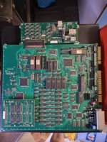
Hi guys, I have a Point Blank 1 cabinet with both Point Blank 1 and 2 pcbs to go in it.
The Point Blank 2 pcb was working fine in this cabinet very briefly (apart from no recoil), but then the pcb failed. I hopefully have someone willing to have a look at the Point Blank 2 board, but in the meantime I have bought a Point Blank 1 pcb.
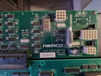
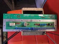
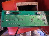
Looking to see exactly how it should be wired up so that the gun sensors work properly. At the moment everything seems to work with the PB1 board apart from the gun sensors. I think some additional wiring is required, between the connections on the V147 Position PCB and the confusingly named V147 EMI Filter Board. But then there are 3 connectors on the V147 that look like something should be plugged in to them (J1 6 pin connector, J2 15 pin connector, J4 9pin connector).
The manual and diagrams I have found online so far seem inconclusive as not every set up is the same. Some seem to be wiring it up without the filter board at all and not every V147 and V147EMI seem to have exactly the same connections.
I have established that the reason the recoil was not working is because the cab seems to be missing a 24v power supply. It just has a standard switcher in place supplying 5v and 12v and then a separate 17v power supply. No idea who put the 17v power supply inside it, or why, as it seems very clear that the recoil needs 24v. I have now sourced a 24v power supply so also need to see exactly how this should be wired up, if possible.
Ideally I want to wire it up so that it's easy to unplug Point Blank 1 and plug in Point Blank 2, when I have that PCB working again, but for now the priority is just to get Point Blank 1 fully working as easily as possible.
I do actually have 2 of the V147 EMI Filterboards.
Thanks in advance for any help.
Danny
The Point Blank 2 pcb was working fine in this cabinet very briefly (apart from no recoil), but then the pcb failed. I hopefully have someone willing to have a look at the Point Blank 2 board, but in the meantime I have bought a Point Blank 1 pcb.
Looking to see exactly how it should be wired up so that the gun sensors work properly. At the moment everything seems to work with the PB1 board apart from the gun sensors. I think some additional wiring is required, between the connections on the V147 Position PCB and the confusingly named V147 EMI Filter Board. But then there are 3 connectors on the V147 that look like something should be plugged in to them (J1 6 pin connector, J2 15 pin connector, J4 9pin connector).
The manual and diagrams I have found online so far seem inconclusive as not every set up is the same. Some seem to be wiring it up without the filter board at all and not every V147 and V147EMI seem to have exactly the same connections.
I have established that the reason the recoil was not working is because the cab seems to be missing a 24v power supply. It just has a standard switcher in place supplying 5v and 12v and then a separate 17v power supply. No idea who put the 17v power supply inside it, or why, as it seems very clear that the recoil needs 24v. I have now sourced a 24v power supply so also need to see exactly how this should be wired up, if possible.
Ideally I want to wire it up so that it's easy to unplug Point Blank 1 and plug in Point Blank 2, when I have that PCB working again, but for now the priority is just to get Point Blank 1 fully working as easily as possible.
I do actually have 2 of the V147 EMI Filterboards.
Thanks in advance for any help.
Danny
Last edited: