PCB Repair - Taito Arkanoid
Game: Original Taito Arkanoid pcb.
Purchase Description: Untested.
Fault on Receipt: Dead.
I recently picked up another original Arkanoid board. The
board itself was a bit dirty but otherwise complete. There seems to be no
previous repairs that I could see.
After giving the board a visual checking over, I plugged
it in and find it’s pretty much dead. There’s a clock to pin 6 and the reset is
being held high on pin 26 of the Z80, but apart from that nothing much is going
on.
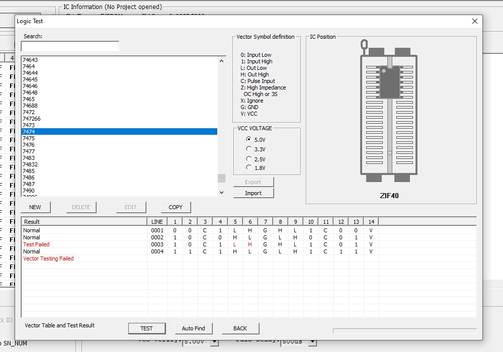
I start at the 74LS74 flip flop at IC76 just after the
12MHz Crystal. The original Arkanoid schematics only show a single output; pin
9 – 6M inverted. The other output (6M) on pin 8 is missing on the schematics
and this is the one that goes via the 7417 at IC11 to the clock pin 6 of the
Z80. I follow the inverted 6M from IC76 which goes to another missing part of
the schematics to the clock pin 3 of the flip flop at IC31 and then onto the
clock pins of 2x LS298’s at IC38 and IC39. I’m getting a high/low reading from
my logic probe at IC38 and IC39, yet the reading is constantly low on the same
connection at the flip flop. I’m thinking perhaps the flip flop is faulty and somehow
pulling the line low a bit, so I remove it and test it. Sure enough the chip is
faulty:-
I reconnect the board, power it up and still a blank
screen of nothing.
Trying to work with incomplete schematics is a bit of a
nightmare, so I had a bit of random probing of various pins with the logic
probe to see what signs of life there might be. A lot of the pins are either
permanently high or low, not much toggling going on. I found that pin 15 of IC49
(74LS298) was floating. It’s the SRA8 output for the screen address bus. I pull
the chip and that too also was also confirmed to be faulty.

I plugged the board in, again absolutely nothing – still
a blank screen.
Considering there is pretty much no life on the board and
nothing on screen, I’m certain I’ve got a sync issue here. A large part of the
sync schematics are missing so I decide to halt the board repair and turn my
attention to “repairing” the schematics.
These original Arkanoid Taito pcb’s have a white solder
mask coating on them and it’s nearly impossible to see where each track goes
to, so I painstakingly spend the next 2 weeks ‘beeping’ out every missing
connection on the schematics and clean up a couple of errors, plus make clearer
some of the labelling. I’ve now got the schematics where I think they are now
pretty much complete, however I can’t guarantee that I’ve missed the odd couple
of connections somewhere or if there are any errors.
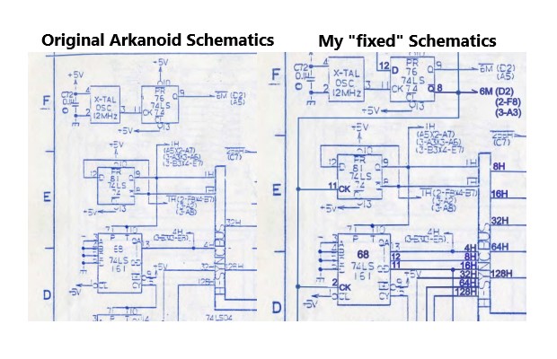
Now armed with some better
schematics, I can clearly see that there’s some counters connected straight
from the previously mentioned flip flop at IC76.

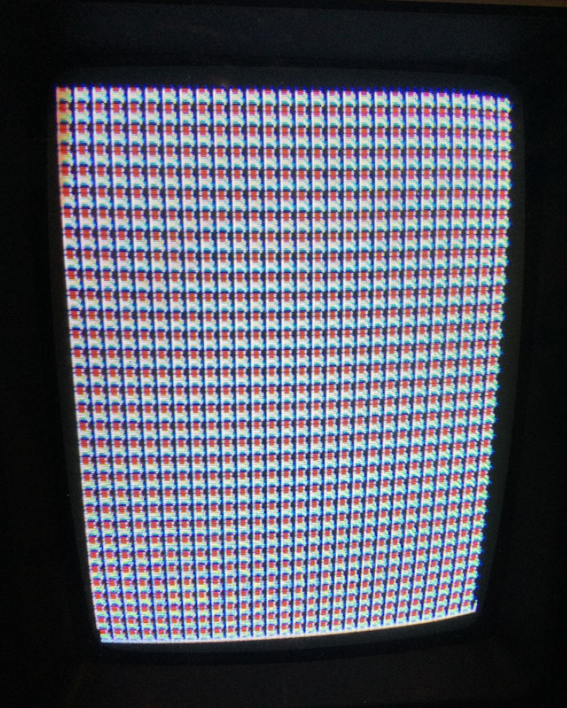
I probe the outputs from the 74LS161’s at IC67
and IC68. Pins 11,12 and 13 on IC68 are all stuck high and I’m certain they are
faulty. I piggyback a good LS161 on top of IC68 and I get this on the screen...

Some life at last! I remove IC68 and sure enough it fails
in the tester…

Whilst fitting a socket for the new 74LS161 I happen to
notice a 1K resistor at the edge of the board that feels a bit ‘springy’. On
closer inspection I can see that it is actually broken, so the resistor at R28
is replaced…

With the broken resistor replaced and a new 74LS161
fitted, the board now powers up to this…
The game is now watchdogging. It’s looking to me like a possible
Ram issue. All 3x TMM2016 Rams are soldered directly to the board so I decide
to de-solder all three of them and test them. The Ram at IC15 tested bad. With
new sockets and good ram, the board powers up to this…

The graphics are corrupt and it looks to me as if it’s
booting straight into test mode. Test mode is normally enabled via Dip Switch 6
and the inputs are controlled by the YM2149F sound chip. I probe all the dip
switch inputs on the YM2149F and every single one is low, regardless of the position
of the dip switches. Normally the inputs are high unless the dip switch is ON,
which then pulls that input to GND making it low. It’s clear the YM2149F chip
is faulty. With the old sound chip removed and a new replacement fitted, the
game now boots up and appears to run, however the graphics are messed up…

On the plus side, the sound and volume appear to be
working and the game credits up.
Getting back to my “fixed” schematics, I can see the 3
graphic Roms are controlled by 4x 74LS298’s (IC47, IC48, IC49 and IC50). I’ve
already replaced IC49 so I check out the other 3. Now that the game is actually
running there is now plenty of activity on the pins, however the output on pins
13 and 15 of IC50 are permanently high. It’s time to remove this sucker and fit
a replacement. It’s looking a lot better but there’s still more work to do…

There’s still some graphic issues and the Vaus is just
over half way up the screen. The Aliens are also in the wrong position. I had
this same issue from a previous Arkanoid repair:- http://www.ukvac.com/forum/tournament-arkanoid-pcb-repair_topic383247.html, and I’m certain it’s
going to be those two 74LS669's at IC52 and IC65 causing the problem. I probe
the output pins 11-14 on both IC’s. Pins 13 and 14 are stuck low on IC52 and
pin 11 is stuck low on IC65. The offending chips are removed and two
replacements fitted. This fixes the positioning problem.
I’m still getting graphic issues and the text is not
right, the bottom part of the text is cut off and the top part looks repeated
(you can see it clearly with the “Game Over” text). Also, when the game is playing if a power up capsule falls down the screen a glitchly graphic line goes
up the screen at the same speed (like if it is inverted), a slightly weird
effect.

The above graphic and text issue is actually caused by a
loss of the 2H sync. But how did I eventually work this out? Read on…
I must admit, this part of this repair took me ages to
track down. After testing
everything in the horizontal position circuit I had a suspicion that perhaps
I’ve got a problem with the sync somewhere.
Let’s look at the original schematics again and my
“fixed” schematics. Notice how there is no 2H to the horizontal sync bus…
I suspected pin 14 of the LS161 at IC68 may have been the
2H. There was certainly activity on this pin when checking it with the logic
probe, however despite me going over the board with a fine toothcomb and
checking every pin on every other chip on the board I could not find where this
pin went to. The chip was definitely good, I’ve already replaced it. If you
look at the original schematics it didn’t look to me like there was meant to be a
connection to pin 14 as the 4H track writing was in the way where a
possible line for 2H would go. I simply assumed that it was actually unused and
meant to be disconnected. So I started looking elsewhere and got absolutely nowhere!
Fast forward several months and I find a thread on KLOV
that member “mdeslaur” has also done a complete Arkanoid Schematics. Top stuff
 His complete schematic is available here:- http://archive.org/details/arkanoid-schematic-complete
At the time of writing this log, there are a few errors
on his schematics, however it’s far better and neater than my attempt. I printed off his schematics and spend a nice relaxing Sunday evening looking over them.
This catches my eye, the 74LS20 circled in red is
completely missing from my own “fixed” version of the schematics and it looks
like there is actually meant to be 2H to the sync bus too! (circled in green).

However, something doesn’t look right with the circled
LS20, I’m sure this half of the IC69 is actually meant to be somewhere else.
The correct half of IC69 is actually here…

So it’s an error. The LS20 in the Vertical Sync circuit
is actually IC75. However, look what is connected to pin 2 of the LS20 at IC69!
Yep, 2H sync! On the original schematics pin 2 is not shown as connected. My
logic probe shows pin 2 of IC69 as floating. I grab my multi-meter and do a
continuity test between pin 14 of the 161 (IC68) and pin 2 of the 20 (IC69), it
is not connected. Looks like I’ve got a broken track between the two points.
Thankfully these two chips are right next to each other so I can jump a small wire
bridge between the two pins on the underside of the pcb.
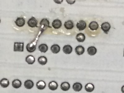
I’m guessing here
that when I removed the original faulty 161 chip I must have damaged the pad on
pin 14 and it broke the connection.
With the very short wire link repaired, look what I’m
greeted with after months of persistence…

Finally! A fully working game


I must give a big thanks to “mdeslaur” for his fine work
on fixing the Arkanoid schematics, it was the final piece in the puzzle that
allowed me to finish this repair. When I look back at my “fixed” schematics I
realised that there were a fair few things I missed and a couple of errors as
well. I’ve already dropped mdeslaur a message on KLOV so hopefully he can make
the minor updates and corrections to his schematics as I certainly recommend
people use his schematics, rather than mine!
Parts needed for this repair:-
·
1x 74LS74 TTL chip
·
1x 74LS161 TTL chip
·
2x 74LS298 TTL chips
·
2x 74LS669 TTL chips
·
1x 6116 Ram (to replace TMM2016)
·
1x YM2149F Sound Chip
·
1x 1k Resistor
Edit December 2022: I've recently had a PM from mdeslaur saying he's updated his schematics
Top work from him
 . Here's a reminder again for the full fixed Arkanoid schematics:-
http://archive.org/details/arkanoid-schematic-complete
qjuk2022-12-18 13:12:29
Game: Original Taito Arkanoid pcb.
Purchase Description: Untested.
Fault on Receipt: Dead.
I recently picked up another original Arkanoid board. The
board itself was a bit dirty but otherwise complete. There seems to be no
previous repairs that I could see.
After giving the board a visual checking over, I plugged
it in and find it’s pretty much dead. There’s a clock to pin 6 and the reset is
being held high on pin 26 of the Z80, but apart from that nothing much is going
on.
I start at the 74LS74 flip flop at IC76 just after the
12MHz Crystal. The original Arkanoid schematics only show a single output; pin
9 – 6M inverted. The other output (6M) on pin 8 is missing on the schematics
and this is the one that goes via the 7417 at IC11 to the clock pin 6 of the
Z80. I follow the inverted 6M from IC76 which goes to another missing part of
the schematics to the clock pin 3 of the flip flop at IC31 and then onto the
clock pins of 2x LS298’s at IC38 and IC39. I’m getting a high/low reading from
my logic probe at IC38 and IC39, yet the reading is constantly low on the same
connection at the flip flop. I’m thinking perhaps the flip flop is faulty and somehow
pulling the line low a bit, so I remove it and test it. Sure enough the chip is
faulty:-
I reconnect the board, power it up and still a blank
screen of nothing.
Trying to work with incomplete schematics is a bit of a
nightmare, so I had a bit of random probing of various pins with the logic
probe to see what signs of life there might be. A lot of the pins are either
permanently high or low, not much toggling going on. I found that pin 15 of IC49
(74LS298) was floating. It’s the SRA8 output for the screen address bus. I pull
the chip and that too also was also confirmed to be faulty.
I plugged the board in, again absolutely nothing – still
a blank screen.
Considering there is pretty much no life on the board and
nothing on screen, I’m certain I’ve got a sync issue here. A large part of the
sync schematics are missing so I decide to halt the board repair and turn my
attention to “repairing” the schematics.
These original Arkanoid Taito pcb’s have a white solder
mask coating on them and it’s nearly impossible to see where each track goes
to, so I painstakingly spend the next 2 weeks ‘beeping’ out every missing
connection on the schematics and clean up a couple of errors, plus make clearer
some of the labelling. I’ve now got the schematics where I think they are now
pretty much complete, however I can’t guarantee that I’ve missed the odd couple
of connections somewhere or if there are any errors.
Now armed with some better
schematics, I can clearly see that there’s some counters connected straight
from the previously mentioned flip flop at IC76.
I probe the outputs from the 74LS161’s at IC67
and IC68. Pins 11,12 and 13 on IC68 are all stuck high and I’m certain they are
faulty. I piggyback a good LS161 on top of IC68 and I get this on the screen...
Some life at last! I remove IC68 and sure enough it fails
in the tester…
Whilst fitting a socket for the new 74LS161 I happen to
notice a 1K resistor at the edge of the board that feels a bit ‘springy’. On
closer inspection I can see that it is actually broken, so the resistor at R28
is replaced…
With the broken resistor replaced and a new 74LS161
fitted, the board now powers up to this…
The game is now watchdogging. It’s looking to me like a possible
Ram issue. All 3x TMM2016 Rams are soldered directly to the board so I decide
to de-solder all three of them and test them. The Ram at IC15 tested bad. With
new sockets and good ram, the board powers up to this…
The graphics are corrupt and it looks to me as if it’s
booting straight into test mode. Test mode is normally enabled via Dip Switch 6
and the inputs are controlled by the YM2149F sound chip. I probe all the dip
switch inputs on the YM2149F and every single one is low, regardless of the position
of the dip switches. Normally the inputs are high unless the dip switch is ON,
which then pulls that input to GND making it low. It’s clear the YM2149F chip
is faulty. With the old sound chip removed and a new replacement fitted, the
game now boots up and appears to run, however the graphics are messed up…
On the plus side, the sound and volume appear to be
working and the game credits up.
Getting back to my “fixed” schematics, I can see the 3
graphic Roms are controlled by 4x 74LS298’s (IC47, IC48, IC49 and IC50). I’ve
already replaced IC49 so I check out the other 3. Now that the game is actually
running there is now plenty of activity on the pins, however the output on pins
13 and 15 of IC50 are permanently high. It’s time to remove this sucker and fit
a replacement. It’s looking a lot better but there’s still more work to do…
There’s still some graphic issues and the Vaus is just
over half way up the screen. The Aliens are also in the wrong position. I had
this same issue from a previous Arkanoid repair:- http://www.ukvac.com/forum/tournament-arkanoid-pcb-repair_topic383247.html, and I’m certain it’s
going to be those two 74LS669's at IC52 and IC65 causing the problem. I probe
the output pins 11-14 on both IC’s. Pins 13 and 14 are stuck low on IC52 and
pin 11 is stuck low on IC65. The offending chips are removed and two
replacements fitted. This fixes the positioning problem.
I’m still getting graphic issues and the text is not
right, the bottom part of the text is cut off and the top part looks repeated
(you can see it clearly with the “Game Over” text). Also, when the game is playing if a power up capsule falls down the screen a glitchly graphic line goes
up the screen at the same speed (like if it is inverted), a slightly weird
effect.
The above graphic and text issue is actually caused by a
loss of the 2H sync. But how did I eventually work this out? Read on…
I must admit, this part of this repair took me ages to
track down. After testing
everything in the horizontal position circuit I had a suspicion that perhaps
I’ve got a problem with the sync somewhere.
Let’s look at the original schematics again and my
“fixed” schematics. Notice how there is no 2H to the horizontal sync bus…
I suspected pin 14 of the LS161 at IC68 may have been the
2H. There was certainly activity on this pin when checking it with the logic
probe, however despite me going over the board with a fine toothcomb and
checking every pin on every other chip on the board I could not find where this
pin went to. The chip was definitely good, I’ve already replaced it. If you
look at the original schematics it didn’t look to me like there was meant to be a
connection to pin 14 as the 4H track writing was in the way where a
possible line for 2H would go. I simply assumed that it was actually unused and
meant to be disconnected. So I started looking elsewhere and got absolutely nowhere!
Fast forward several months and I find a thread on KLOV
that member “mdeslaur” has also done a complete Arkanoid Schematics. Top stuff
At the time of writing this log, there are a few errors
on his schematics, however it’s far better and neater than my attempt. I printed off his schematics and spend a nice relaxing Sunday evening looking over them.
This catches my eye, the 74LS20 circled in red is
completely missing from my own “fixed” version of the schematics and it looks
like there is actually meant to be 2H to the sync bus too! (circled in green).
However, something doesn’t look right with the circled
LS20, I’m sure this half of the IC69 is actually meant to be somewhere else.
The correct half of IC69 is actually here…
So it’s an error. The LS20 in the Vertical Sync circuit
is actually IC75. However, look what is connected to pin 2 of the LS20 at IC69!
Yep, 2H sync! On the original schematics pin 2 is not shown as connected. My
logic probe shows pin 2 of IC69 as floating. I grab my multi-meter and do a
continuity test between pin 14 of the 161 (IC68) and pin 2 of the 20 (IC69), it
is not connected. Looks like I’ve got a broken track between the two points.
Thankfully these two chips are right next to each other so I can jump a small wire
bridge between the two pins on the underside of the pcb.
I’m guessing here
that when I removed the original faulty 161 chip I must have damaged the pad on
pin 14 and it broke the connection.
With the very short wire link repaired, look what I’m
greeted with after months of persistence…
Finally! A fully working game
I must give a big thanks to “mdeslaur” for his fine work
on fixing the Arkanoid schematics, it was the final piece in the puzzle that
allowed me to finish this repair. When I look back at my “fixed” schematics I
realised that there were a fair few things I missed and a couple of errors as
well. I’ve already dropped mdeslaur a message on KLOV so hopefully he can make
the minor updates and corrections to his schematics as I certainly recommend
people use his schematics, rather than mine!
Parts needed for this repair:-
·
1x 74LS74 TTL chip
·
1x 74LS161 TTL chip
·
2x 74LS298 TTL chips
·
2x 74LS669 TTL chips
·
1x 6116 Ram (to replace TMM2016)
·
1x YM2149F Sound Chip
·
1x 1k Resistor
Edit December 2022: I've recently had a PM from mdeslaur saying he's updated his schematics
Top work from him
http://archive.org/details/arkanoid-schematic-complete
qjuk2022-12-18 13:12:29
")


