

I've got a watch-dogging Asteroids on my bench and I've done everything to it but what I should have done in the first place was the obvious. Replacing sockets, RAMs and ROMs is all very good but if the first buffer IC is the wrong type then you're not going to get very far! The summary of this rant and knowledge share is; Asteroids PCBs can have 1 of 2 different buffers at E3 - either a LS245 or a DP8304. Depending on which version PCB you have you need to use the correct one... as they are not interchangeable. They clearly have different pinouts and the traces on the PCB are setup for one or the other. EDIT: But Atari did something clever in that they provided sockets for both buffers! I guess this was so that they could use whichever TTL was cheapest / available at time of production. So be sure to desolder the socket and then select the correct holes for your buffer.
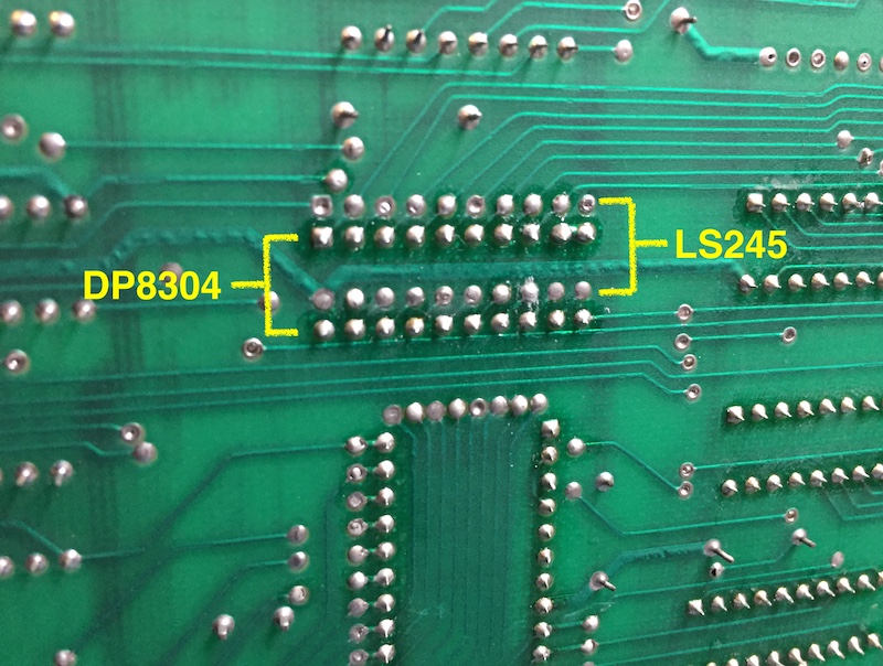
I can see they have different pinouts on the schematics but, for whatever reason, I totally ignored that fact for a good number of days. I could see activity on all the address lines, data lines and the zero page RAMs at D2/E2 seemed like they were getting the correct signals but I couldn't understand why it was still watch-dogging and not progressing further. I ended up fitting a new XR resistor-less header on my Arduino ICT and when I tried to test a particular RAM I could see activity and after looking at the data lines it was even receiving and returning the same data. The problem was that the data it received didn't match the data that the CPU was sending! It was at that point that I unplugged all the clever tools I'd been using, reached for my multimeter on continuity and buzzed out the connection from the CPU to the buffer and then the buffer to the RAM. I then realised that the data lines going into the buffer did not match up with the data lines going to the RAM and that data line D0 was connected to the LS245 Output Enable (OE) pin! It was only at that moment that I finally understood this PCB was currently configured to use the DP8304 socket and not the LS245.
So there you go. Do the simple things first! In my defence I'd checked other things like the NMI circuit, the watch dog circuit and the clock, as well as swapping out the CPU for a known worker, just didn't bother buzzing out the connection between the CPU and the first RAMs.
You live and learn.
Nes4life2017-11-12 07:59:24
I can see they have different pinouts on the schematics but, for whatever reason, I totally ignored that fact for a good number of days. I could see activity on all the address lines, data lines and the zero page RAMs at D2/E2 seemed like they were getting the correct signals but I couldn't understand why it was still watch-dogging and not progressing further. I ended up fitting a new XR resistor-less header on my Arduino ICT and when I tried to test a particular RAM I could see activity and after looking at the data lines it was even receiving and returning the same data. The problem was that the data it received didn't match the data that the CPU was sending! It was at that point that I unplugged all the clever tools I'd been using, reached for my multimeter on continuity and buzzed out the connection from the CPU to the buffer and then the buffer to the RAM. I then realised that the data lines going into the buffer did not match up with the data lines going to the RAM and that data line D0 was connected to the LS245 Output Enable (OE) pin! It was only at that moment that I finally understood this PCB was currently configured to use the DP8304 socket and not the LS245.
So there you go. Do the simple things first! In my defence I'd checked other things like the NMI circuit, the watch dog circuit and the clock, as well as swapping out the CPU for a known worker, just didn't bother buzzing out the connection between the CPU and the first RAMs.
You live and learn.
Nes4life2017-11-12 07:59:24
