

It's been a while since I posted one of these, this one has been wrapped up today...
A few months back I offered to look at a few Breakout PCB's from a forum member on UKVac.com, they were in an unknown state but the owner has an Atari cab and it's no fun having a cab with broken PCB's. Challenge accepted!
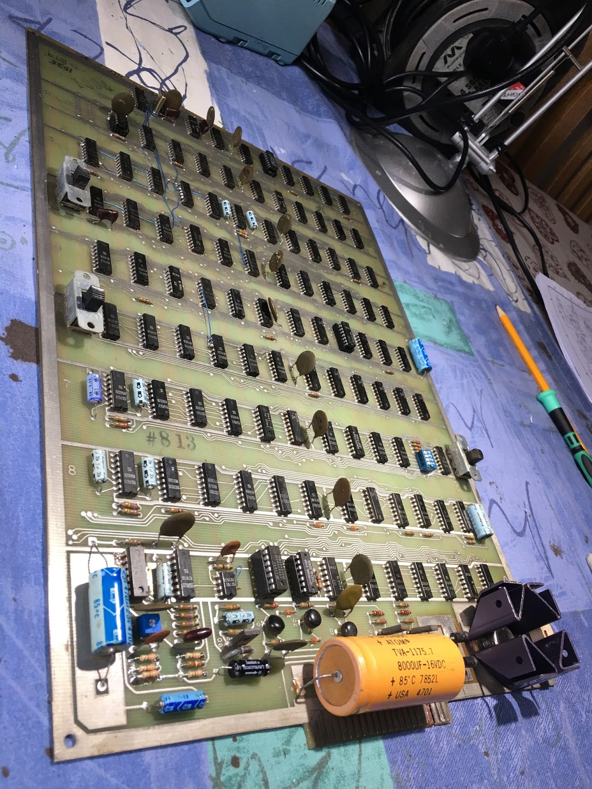
Once they arrived I made a quick overview/assessment of the PCB's. There were two Atari PCBs and a bootleg/clone board, here's the info about the one I repaired in this post.
Atari PCB1 (Orange filter cap) - Factory Wire mods.
Missing LM323 and heatsink.
Missing Electrolytic Cap - C22 10uF
Missing J1 - 74174 - Sync & Video Combining for final output stage.
Missing E9 - 7404 - 1/2 Player start logic, 2player control logic.
Missing R50 - Volume pot 10K
Pin 4 underside of edge connector burnt away. Wire link mods made.
I decided to tackle what I call Atari PCB1 first, the owner was keen to have an original PCB so the bootleg was left to one side even though it was now known to partially work.
I fitted the missing 74174, 7404 the Capacitor at C22 and the missing volume pot. at R50.
I hacked some power wires to the PCB for the 5vDC logic, I also added 12vDC in place of AC to run the audio circuit.
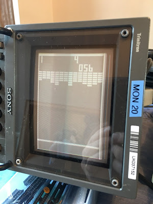
The game fired up on my test monitor, the scores would flicker and there was an odd ripple that would move through the video image, mainly showing itself on the left side of the screen. This turned out to be a 9312 at K5. I had to remove one of these IC's from the other Breakout PCB as these are now obsolete and there is no direct replacement. Once fitted, this fault was fixed.

Something I noticed was that the video signal was not showing bright whites as I was expecting to see, it was more of a Gray colour and didn't quite look right.
After looking at the values of resistors in the final video section where the different parts of the video are joined (Playfield, Scores etc.) I noticed all the resistors were different values to what is shown on the schematics from the operations and maintenance manuals available on the Internet. This is a Revision C board while the schematics I had were for Revision F, there are a handful of factory wire mods across the PCB which must have been fixed in later revisions.
I changed 4 resistors and added a 5th that is shown in later PCB revisions and the image turned into the bright white I was expecting.
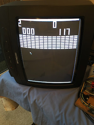
At this point I populated the missing LM323K voltage regulator along with heatsink, all that was left to do was fix the Edge connector, something I'd never tackled before.
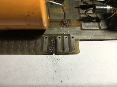
I had a gentle scrape to remove all the old burnt mess and was left with the following:
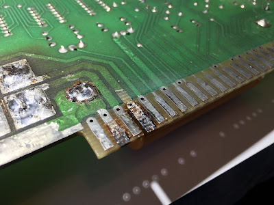
I decided to use Epoxy glue to 'fill' the PCB back into the size it needed to be, as some of the PCB had been eaten away by the burning.
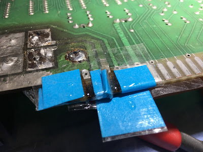
The photo above shows the area masked off and filled with glue, this was left for a day to cure hard. Once sanded it was looking better, I just needed to replace the copper tracks.

I used some self adhesive copper tape which I found on ebay, I simple purchased a 'sample' for 99p which will give me a lifetimes worth of tape fore edge repairs, once applied (I used very small amounts of epoxy glue) I used some old cut offs from capacitor legs, to loop through the board where I would solder onto.
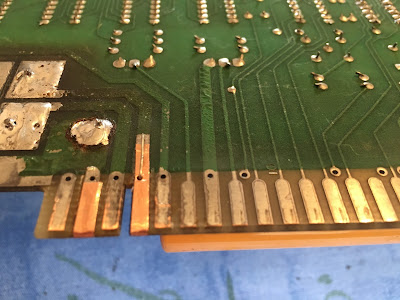
Once soldered into place it looked good and I'm fairly confident it will be strong enough for normal use.
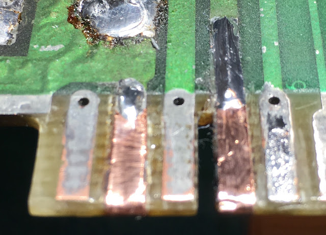
So that was it. I tested the game for all functions and it's ready to be returned to its owner. Another PCB saved to make an old arcade live again. Thanks for reading.

smarty2018-02-18 14:21:01
A few months back I offered to look at a few Breakout PCB's from a forum member on UKVac.com, they were in an unknown state but the owner has an Atari cab and it's no fun having a cab with broken PCB's. Challenge accepted!
Once they arrived I made a quick overview/assessment of the PCB's. There were two Atari PCBs and a bootleg/clone board, here's the info about the one I repaired in this post.
Atari PCB1 (Orange filter cap) - Factory Wire mods.
Missing LM323 and heatsink.
Missing Electrolytic Cap - C22 10uF
Missing J1 - 74174 - Sync & Video Combining for final output stage.
Missing E9 - 7404 - 1/2 Player start logic, 2player control logic.
Missing R50 - Volume pot 10K
Pin 4 underside of edge connector burnt away. Wire link mods made.
I decided to tackle what I call Atari PCB1 first, the owner was keen to have an original PCB so the bootleg was left to one side even though it was now known to partially work.
I fitted the missing 74174, 7404 the Capacitor at C22 and the missing volume pot. at R50.
I hacked some power wires to the PCB for the 5vDC logic, I also added 12vDC in place of AC to run the audio circuit.

The game fired up on my test monitor, the scores would flicker and there was an odd ripple that would move through the video image, mainly showing itself on the left side of the screen. This turned out to be a 9312 at K5. I had to remove one of these IC's from the other Breakout PCB as these are now obsolete and there is no direct replacement. Once fitted, this fault was fixed.

Something I noticed was that the video signal was not showing bright whites as I was expecting to see, it was more of a Gray colour and didn't quite look right.
After looking at the values of resistors in the final video section where the different parts of the video are joined (Playfield, Scores etc.) I noticed all the resistors were different values to what is shown on the schematics from the operations and maintenance manuals available on the Internet. This is a Revision C board while the schematics I had were for Revision F, there are a handful of factory wire mods across the PCB which must have been fixed in later revisions.
I changed 4 resistors and added a 5th that is shown in later PCB revisions and the image turned into the bright white I was expecting.

At this point I populated the missing LM323K voltage regulator along with heatsink, all that was left to do was fix the Edge connector, something I'd never tackled before.
I had a gentle scrape to remove all the old burnt mess and was left with the following:

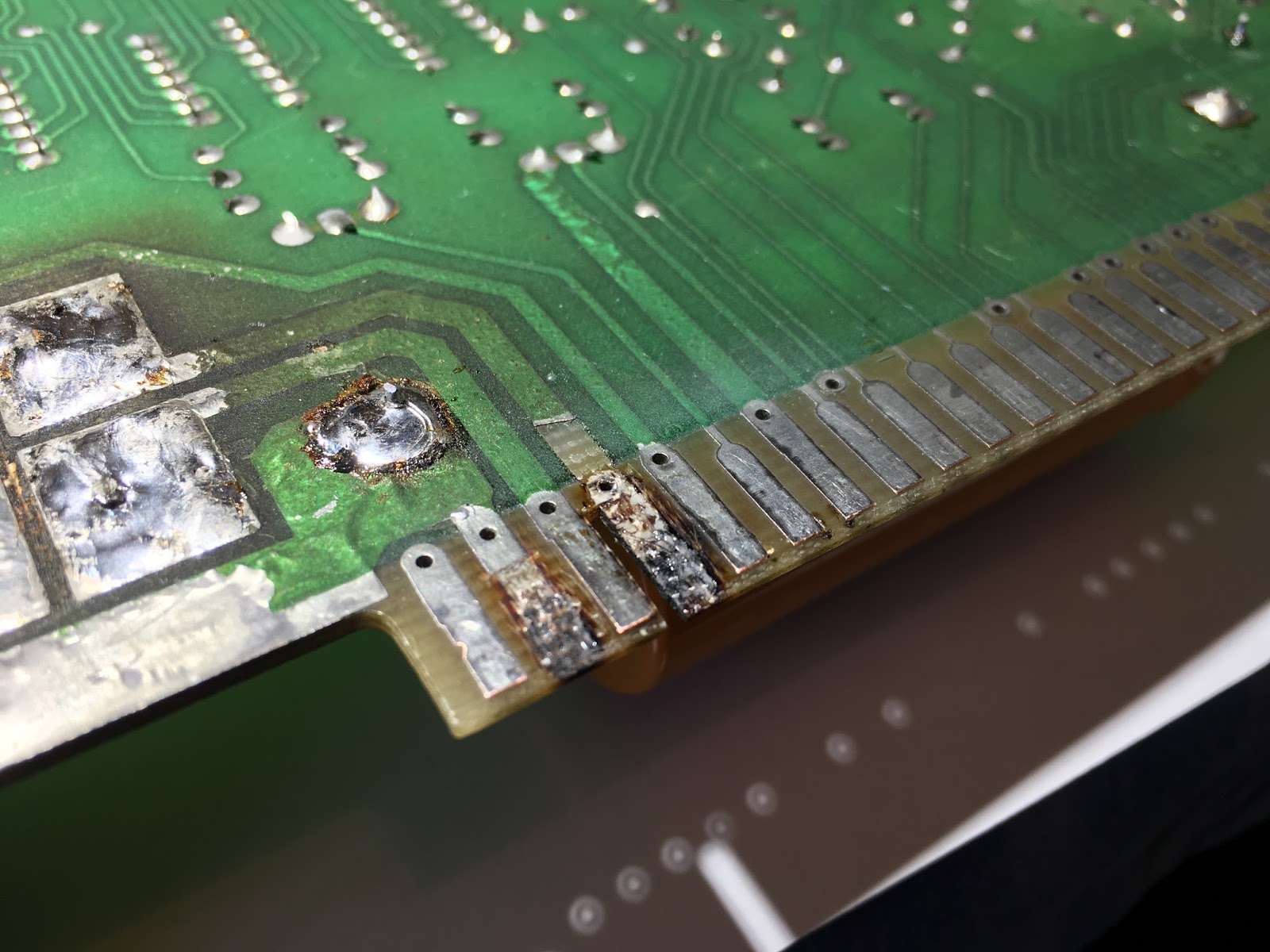
I decided to use Epoxy glue to 'fill' the PCB back into the size it needed to be, as some of the PCB had been eaten away by the burning.

The photo above shows the area masked off and filled with glue, this was left for a day to cure hard. Once sanded it was looking better, I just needed to replace the copper tracks.

I used some self adhesive copper tape which I found on ebay, I simple purchased a 'sample' for 99p which will give me a lifetimes worth of tape fore edge repairs, once applied (I used very small amounts of epoxy glue) I used some old cut offs from capacitor legs, to loop through the board where I would solder onto.

Once soldered into place it looked good and I'm fairly confident it will be strong enough for normal use.

So that was it. I tested the game for all functions and it's ready to be returned to its owner. Another PCB saved to make an old arcade live again. Thanks for reading.
smarty2018-02-18 14:21:01


