So, a (very) long time ago I offered to look at a pair of Chase HQ boardsets. Seemed a bit of fun – I thought I could do a bit of board swapping, score an easy fix and feel chuffed with myself.

Nope.
One boardset wouldn’t boot.
The other booted with a sound CPU ‘stop’ fault, the colours were wrong and the sprites were all messed up.
Swapping the video PCB over presented even more sprite faults.
So that’s 4/4 duff PCBs

I looked at the non-booting board first. I checked the 68K reset line and I could see it was low. Whilst there is a typical reset IC, it passes through a custom – presumably for a watchdog or something. It didn’t seem to be getting out the other end.

So I bypassed it
 . Naughty, perhaps, but I’m sure the owner can flip the mains if the game ever crashes.
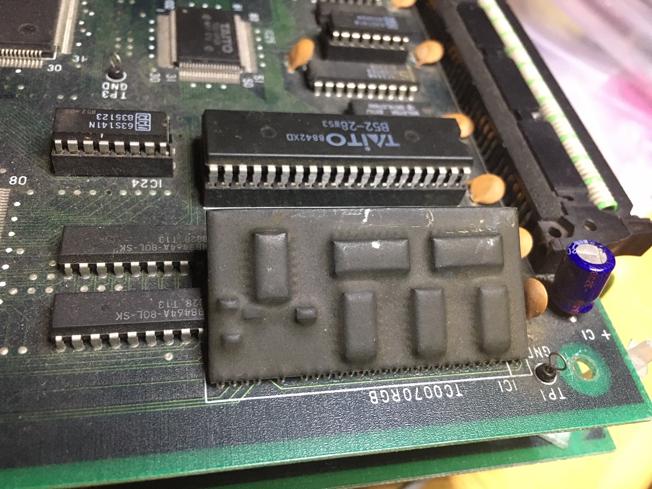
Next, the lack of colours was simply a broken pin from the RGB DAC custom (that’s often snapped off completely, so watch for that if buying an ‘untested’ PCB).
After that, the CPU board worked great – sound, colours, the lot.
25% fixed…
Video PCB #1 next (dodgy sprites).

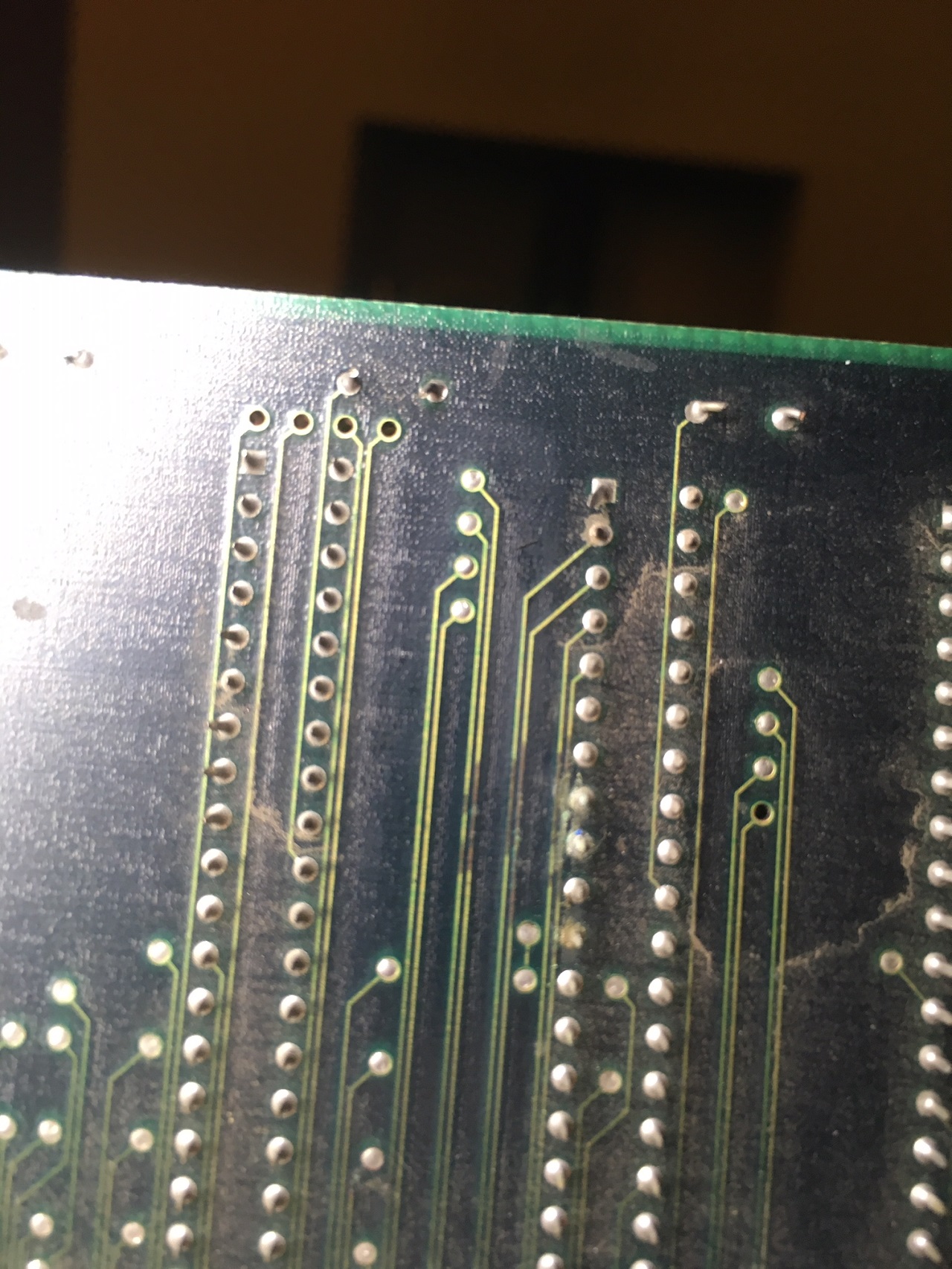
I stuck the scope on the address lines for the mask ROMs related to the sprites and I could see dead address lines. Looking at the board, there was noticeable track-rot. With two dead tracks linked, the sprites were fixed.

50% fixed...
Next, the other video PCB. This was intermittent – the object layer corrupting itself over time.
I looked again at the object ROM address lines on the scope. When zoomed out to a long timebase, even though it was a blur of activity, I could see the underlying data starting to change as the intermittent fault appeared. The next job was to trace back to the source, which involved looking at outputs vs inputs of ICs – I think I went back through 5 pages of schematics before I arrived at a bad counter IC (not totally dead either, just to add confusion).

75% Fixed.
Finally – the Sound Stop Error. This is where I gave up for a year

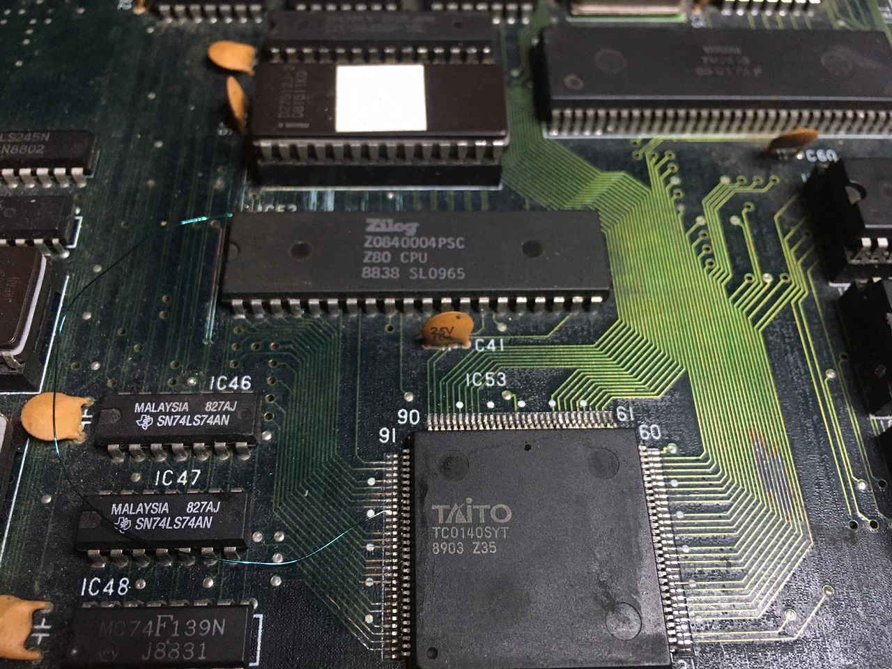
Anyway, at bootup, the master CPU talks to the sound Z80 to check it’s alive. This is done via the SYT custom IC. It’s not the easiest thing to debug as the main CPU sends a sound code occasionally and then otherwise the link is very busy sending FIFO checks, plus both sides are on CPU buses, so it requires a bit of triggering and bus deciphering (MAME helps).

Anyway, probing the Z80, it could be observed that the addresses were just cycling in an upwards-counting manner, so it wasn’t working right. No interrupts were occurring either (the YM2610 will send these once running).
The SYT custom handles the addressing for the Z80, allowing it to select ROM, RAM, YM2610 or cross-comms by accessing upper address locations on the memory bus. After a lot of probing I found that three address lines were broken from the Z80 to the IC and also to the RAM/ROM.
With these fixed, the Sound Stop error was gone and I could see far more normal activity (random-looking address accesses, interrupts firing from the YM and outputs from the YM).
But still no sound.
After far too many mis-steps (staring at the cross-comms, thinking no sound codes were going across the link), I realised that the OPO line was live from the YM2610 IC to the YM3016 DAC and there was an output, it was just rather small. The TL074 Op-amp afterwards was stuck at -5V for the two audio output channels. With this fixed, success!

4/4 boards fixed.
And 1 lesson learned – don’t fix boards for other people as it’s never as easy as you hope
But, to add one more, I bought myself a triple 68k proto Chase HQ (to try to emulate), which arrived with a video fault, however that was just a bad interconnect. But that's not relevant to normal boards as as the proto has DIP socket to ribbon cable adaptors everywhere as there's no mask ROMS, but dozens of EPROMs.

Anyway, might be something of interest. Such an ordeal, I had to post about it
John Bennett2020-11-07 23:58:10
Nope.
One boardset wouldn’t boot.
The other booted with a sound CPU ‘stop’ fault, the colours were wrong and the sprites were all messed up.
Swapping the video PCB over presented even more sprite faults.
So that’s 4/4 duff PCBs
I looked at the non-booting board first. I checked the 68K reset line and I could see it was low. Whilst there is a typical reset IC, it passes through a custom – presumably for a watchdog or something. It didn’t seem to be getting out the other end.
So I bypassed it
Next, the lack of colours was simply a broken pin from the RGB DAC custom (that’s often snapped off completely, so watch for that if buying an ‘untested’ PCB).
After that, the CPU board worked great – sound, colours, the lot.
25% fixed…
Video PCB #1 next (dodgy sprites).
I stuck the scope on the address lines for the mask ROMs related to the sprites and I could see dead address lines. Looking at the board, there was noticeable track-rot. With two dead tracks linked, the sprites were fixed.
50% fixed...
Next, the other video PCB. This was intermittent – the object layer corrupting itself over time.
I looked again at the object ROM address lines on the scope. When zoomed out to a long timebase, even though it was a blur of activity, I could see the underlying data starting to change as the intermittent fault appeared. The next job was to trace back to the source, which involved looking at outputs vs inputs of ICs – I think I went back through 5 pages of schematics before I arrived at a bad counter IC (not totally dead either, just to add confusion).
75% Fixed.
Finally – the Sound Stop Error. This is where I gave up for a year
Anyway, at bootup, the master CPU talks to the sound Z80 to check it’s alive. This is done via the SYT custom IC. It’s not the easiest thing to debug as the main CPU sends a sound code occasionally and then otherwise the link is very busy sending FIFO checks, plus both sides are on CPU buses, so it requires a bit of triggering and bus deciphering (MAME helps).
Anyway, probing the Z80, it could be observed that the addresses were just cycling in an upwards-counting manner, so it wasn’t working right. No interrupts were occurring either (the YM2610 will send these once running).
The SYT custom handles the addressing for the Z80, allowing it to select ROM, RAM, YM2610 or cross-comms by accessing upper address locations on the memory bus. After a lot of probing I found that three address lines were broken from the Z80 to the IC and also to the RAM/ROM.
With these fixed, the Sound Stop error was gone and I could see far more normal activity (random-looking address accesses, interrupts firing from the YM and outputs from the YM).
But still no sound.
After far too many mis-steps (staring at the cross-comms, thinking no sound codes were going across the link), I realised that the OPO line was live from the YM2610 IC to the YM3016 DAC and there was an output, it was just rather small. The TL074 Op-amp afterwards was stuck at -5V for the two audio output channels. With this fixed, success!
4/4 boards fixed.
And 1 lesson learned – don’t fix boards for other people as it’s never as easy as you hope
But, to add one more, I bought myself a triple 68k proto Chase HQ (to try to emulate), which arrived with a video fault, however that was just a bad interconnect. But that's not relevant to normal boards as as the proto has DIP socket to ribbon cable adaptors everywhere as there's no mask ROMS, but dozens of EPROMs.
Anyway, might be something of interest. Such an ordeal, I had to post about it
John Bennett2020-11-07 23:58:10