Hello,
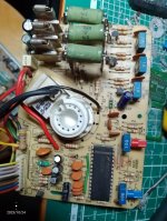
I'm working on this conversion. The chassis is an Polo 2 for 15" CRTs. The Neck board had an mini socket so I replaced it with an 25-28" Polo 2 neck board. The chassis is now married to an MTC9000 CRT Samsung 51GGD95X-TC 20". The CRT itself is working great, have been tested before. The chassis has been tested before with original 15" CRT and it worked well too.
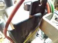
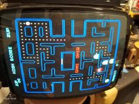
The image I get is dimm, maybe a little brighter on top and way out of focus on the sides. Voltage on the middle pins from the yoke connector is 105V (B+?). As I can see from the schematics, there are a lot of jumpers to set in order to set it to different voltages. I have no ideea what to do here. The Flyback is HR7383 or HR 7389 hard to read. I know it is for 110° and the CRT is 90° but it should still work.
So far I changed the folowing:
Neck board: R35 4.7ohm (With Lower values like 1 Ohm or 2.7 Ohm the Image was way to bright)
Chassis: C58 1000uF (was 2200uF),
C97 0.47uF (was 0.33uF),
C99 6.8nF (was 4.7nF).
Nothing else has been changed so far.
If you know what else must be changed or if the values I put in are wrong please do let me know. I apreciate any help. I can check the resistence on the yoke if is important to know.
Thank you.
Schematics PDF
I'm working on this conversion. The chassis is an Polo 2 for 15" CRTs. The Neck board had an mini socket so I replaced it with an 25-28" Polo 2 neck board. The chassis is now married to an MTC9000 CRT Samsung 51GGD95X-TC 20". The CRT itself is working great, have been tested before. The chassis has been tested before with original 15" CRT and it worked well too.
The image I get is dimm, maybe a little brighter on top and way out of focus on the sides. Voltage on the middle pins from the yoke connector is 105V (B+?). As I can see from the schematics, there are a lot of jumpers to set in order to set it to different voltages. I have no ideea what to do here. The Flyback is HR7383 or HR 7389 hard to read. I know it is for 110° and the CRT is 90° but it should still work.
So far I changed the folowing:
Neck board: R35 4.7ohm (With Lower values like 1 Ohm or 2.7 Ohm the Image was way to bright)
Chassis: C58 1000uF (was 2200uF),
C97 0.47uF (was 0.33uF),
C99 6.8nF (was 4.7nF).
Nothing else has been changed so far.
If you know what else must be changed or if the values I put in are wrong please do let me know. I apreciate any help. I can check the resistence on the yoke if is important to know.
Thank you.
Schematics PDF
Last edited: