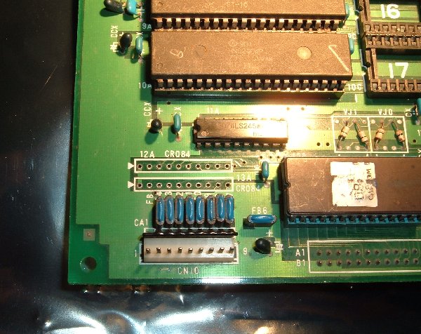
CPS SIL devices.

cliff_poole

Active member
vacBacker
Feedback
6 (100%)
Credits
1,069CR
I have a Strider B and C board which has two broken SIL devices marked CR084. They don't seem to be straight resistor networks from what I can tell. Does anyone know what they are ?. Does CR stand for Capacitor Resistor ?.

CR084a.jpg


CR084b.jpg
 

trm

Who loves you, and who do you love?
Feedback
2 (100%)
Credits
2,877CR
What have you found so far that suggest they're not resistor packs? It might be worth Stanley knifing off the compound given that this one looks permanently dead to see if there are any clues under the coating.

Any idea what function they perform in the circuit or what they are wired to? I can't really see a reason for having a bunch of RC delays in a circuit, but there again I don't design these things :)

Do they look like they're used as a pull-up/down function?
 

cliff_poole

Active member
vacBacker
Feedback
6 (100%)
Credits
1,069CR
By the look of things, they are connected between the connector CN10, then to a 74LS245, and from there I can't really tell.

The game doesn't run and I am unable to read three of the big mask ROMs. I'm just trying to decide whether to go on or to shelve it at the moment.

StriderB.jpg
 

trm

Who loves you, and who do you love?
Feedback
2 (100%)
Credits
2,877CR
From the circuit position I'd guess they are pull-ups. Do you get anything when you meter between pin1 and the others and what's the largest resistance range setting you've tried? Might be worth seeing if one pin of the holes is wired to 5V as that would support the "input pull-ups" idea enough to let you sub some normal resistors.
 

cliff_poole

Active member
vacBacker
Feedback
6 (100%)
Credits
1,069CR
Thanks for the ideas, I think I'd have given up if I hadn't posted
smiley1.gif
.

I'm pretty sure I have got it now. There were two of these on the board and both were broken, the picture above is both sides of the least broken one.

On the PCB, pin 1 goes to +5V and pin 10 (the last pin), goes to ground. I managed to chip off a bit of the black coating and found that the blobs on the back are 10nf capacitors. Pin 1 to pin 2 reads 1K; readings between any other two adjacent pins (except 10), are about 2K, so that looks like 8*1K pull up resistors. I am guessing then that the caps go between the inputs and ground, all commoned together at pin 10 although I am puzzled why there only appear to be four caps looking at the blobs ?.

Anyway, I am satisfied that this is nothing to do with why the game won't run. It is going back on the shelf now as I don't have any 40 pin EPROMS or a spare A board.
 

shep

Active member
vacBacker
Feedback
10 (100%)
Credits
377CR
cps1.jpg


I found them on the Forgotten Worlds schematics. They have 4 inputs and 4 outputs. My guess is that they are capacitor/resistor switch debouncers.
 
Top