You are using an out of date browser. It may not display this or other websites correctly.
You should upgrade or use an alternative browser.
You should upgrade or use an alternative browser.
How to Jamma convert a Sega Dinosaur King
- Thread starter muddymusic
- Start date
Right then.
Acquired a gleaming Dino King from Big Phil, and proceeded to start gutting it tonight. I'm a complete amateur, and the teardown instructions here and in Flinnster's thread have been invaluable. I've hit a wall though: for whatever reason, a few of the pics in the thread don't seem to work anymore. Maybe they would have answered the dumb questions I'm about to ask, will be grateful for any guidance:
I unclipped all the power plugs, and took out the bottom shelf.
What are those things? Are they the PSU for the gameboard or does one of them feed the monitor? If it's the former, can I just unscrew both of those bits and get rid?
Where is the monitor power?
I see a VGA cable going into the top on the left hand side, and another wire coming from the right hand side, and down into the back of the power/test/degauss box. Like an idiot, I unplugged those wires too in trying to free the loom, but I'm guessing they stay plugged in and somewhere out of that service panel the monitor is fed from the main transformer?
Once you've taken out the main loom for the gameboard, what should be left inside in the cab? I've not removed the loom completely yet, because I'm worried I'll take out something that is meant to stay in there. I'm assuming monitor power and that's it, is that right?

The above is about where I am, except I've got the bottom shelf out and disconnected.
Can Flinn/Muddy/anyone else enlighten me?
Thanks lads.
Acquired a gleaming Dino King from Big Phil, and proceeded to start gutting it tonight. I'm a complete amateur, and the teardown instructions here and in Flinnster's thread have been invaluable. I've hit a wall though: for whatever reason, a few of the pics in the thread don't seem to work anymore. Maybe they would have answered the dumb questions I'm about to ask, will be grateful for any guidance:
I unclipped all the power plugs, and took out the bottom shelf.
What are those things? Are they the PSU for the gameboard or does one of them feed the monitor? If it's the former, can I just unscrew both of those bits and get rid?
Where is the monitor power?
I see a VGA cable going into the top on the left hand side, and another wire coming from the right hand side, and down into the back of the power/test/degauss box. Like an idiot, I unplugged those wires too in trying to free the loom, but I'm guessing they stay plugged in and somewhere out of that service panel the monitor is fed from the main transformer?
Once you've taken out the main loom for the gameboard, what should be left inside in the cab? I've not removed the loom completely yet, because I'm worried I'll take out something that is meant to stay in there. I'm assuming monitor power and that's it, is that right?
The above is about where I am, except I've got the bottom shelf out and disconnected.
Can Flinn/Muddy/anyone else enlighten me?
Thanks lads.
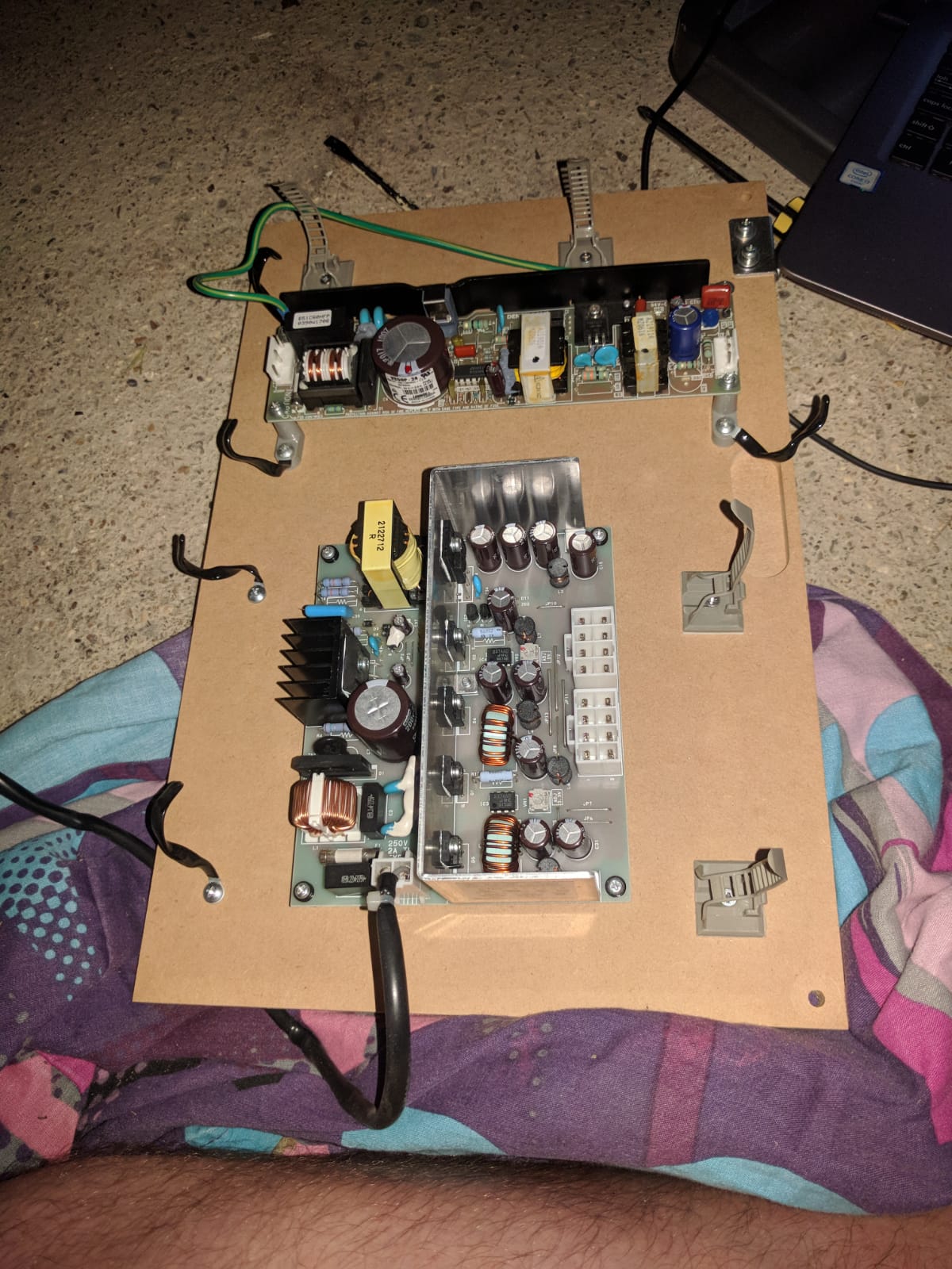
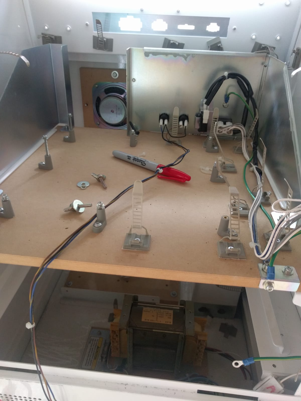
Top pic...
These are the step down transformers. They convert 110v from the big ISO transformer brick at the base of the cab down to 12v, 5v, 3v that the Naomi-esque system board uses. Also the correct voltage for the RFID readers and the card dispenser. Basically remove these from the lower shelf, but keep the shelf as it'll come in useful later.
In JAMMA wiring we effectively replace this lot with a a switching power supply, running from 240v mains not the 110v out from the ISO block (this is left to power the monitor exclusively).
(can't remember if you are doing jamma or just a mame unit)
Monitor Power
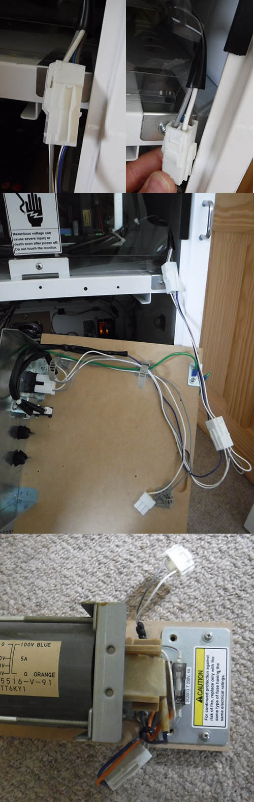
Looking in from the back of the cab, the RGB+sync cable is on your left, in black insulation, and with the VGA plug on the end. It goes into the back left hand corner of the monitor chassis, with a white JST connector in the metal plate under the monitor.
On the other side on the right, you'll see a bunch of white and grey wires with plenty of white JST connectors. These are the power supply (110v) for the monitor and degauss circuit.
The monitor power goes from the ISO transformer at the base, via a flat JST connector to the service panel, then back from the service panel to a large JST connector block with loops on it, and finally up to the JST connector at top right underneath the monitor.
Loom
Take out the sega one. The cab will look a lot more sane without it.
Leave the ISO transformer at the bottom, the service panel on the top shelf and wires going to it, and all earth cables. Leave the door wiring completely alone:

Internal cab metalwork
You can carefully unscrew and remove almost all of the silver metalwork from inside of the cab. The only bits you need are the service panel itself and the connector behind the control panel.
Flinnster2018-08-02 00:43:21
These are the step down transformers. They convert 110v from the big ISO transformer brick at the base of the cab down to 12v, 5v, 3v that the Naomi-esque system board uses. Also the correct voltage for the RFID readers and the card dispenser. Basically remove these from the lower shelf, but keep the shelf as it'll come in useful later.
In JAMMA wiring we effectively replace this lot with a a switching power supply, running from 240v mains not the 110v out from the ISO block (this is left to power the monitor exclusively).
(can't remember if you are doing jamma or just a mame unit)
Monitor Power
Looking in from the back of the cab, the RGB+sync cable is on your left, in black insulation, and with the VGA plug on the end. It goes into the back left hand corner of the monitor chassis, with a white JST connector in the metal plate under the monitor.
On the other side on the right, you'll see a bunch of white and grey wires with plenty of white JST connectors. These are the power supply (110v) for the monitor and degauss circuit.
The monitor power goes from the ISO transformer at the base, via a flat JST connector to the service panel, then back from the service panel to a large JST connector block with loops on it, and finally up to the JST connector at top right underneath the monitor.
Loom
Take out the sega one. The cab will look a lot more sane without it.
Leave the ISO transformer at the bottom, the service panel on the top shelf and wires going to it, and all earth cables. Leave the door wiring completely alone:
Internal cab metalwork
You can carefully unscrew and remove almost all of the silver metalwork from inside of the cab. The only bits you need are the service panel itself and the connector behind the control panel.
Flinnster2018-08-02 00:43:21
The 2 step down transformers on that shelf of yours are for the game board and card dispenser. The long rectangle one is for the card dispenser and gives out 24v (purple wire, black is ground). The other one is for the Dino game board. This gives out 12v (yellow wire), 5v (red wire) and 3.3v (brown wire). The 5v and 3.3v are adjustable, but the max load on the 5v is just 4 amps so probably won’t be of much use. For example the Arkanoid board I want to use needs at least 7A on 5v so I’m going to install a switch mode PSU instead to handle it. I wouldn’t of thought that those two transformers will be of any use to you so you’ll probably end up getting rid of them.
The monitor is powered directly from the chunky 100v transformer at the bottom of the cabinet. It’s a grey and white wire. If you follow the wire from the bottom it goes up to the main switch of the shelf with the Dino game board, from there it splits and one end goes up to the monitor, the other end to the two previously mentioned transformers on the shelf below (the ones that you’ll probably get rid of). I intend to keep all the original 100v wiring in my cabs along with degaussing switch and simply use it to power the monitor.
Edit to add: I intend to add my switch mode power supply into 230v and mount it at the bottom of the cabinet near to the 100v transformer. As mentioned by everyone else, this frees up another shelf inside the machine.qjuk2018-08-02 01:38:15
Thanks SO MUCH for the info, guys.
Stuck my head in the garage before work today, and the main loom appears to be fully out now. The JAMMA loom looks a lot less scary than that beast, jeeze.
Would like to double check a few more things, if you don't mind?
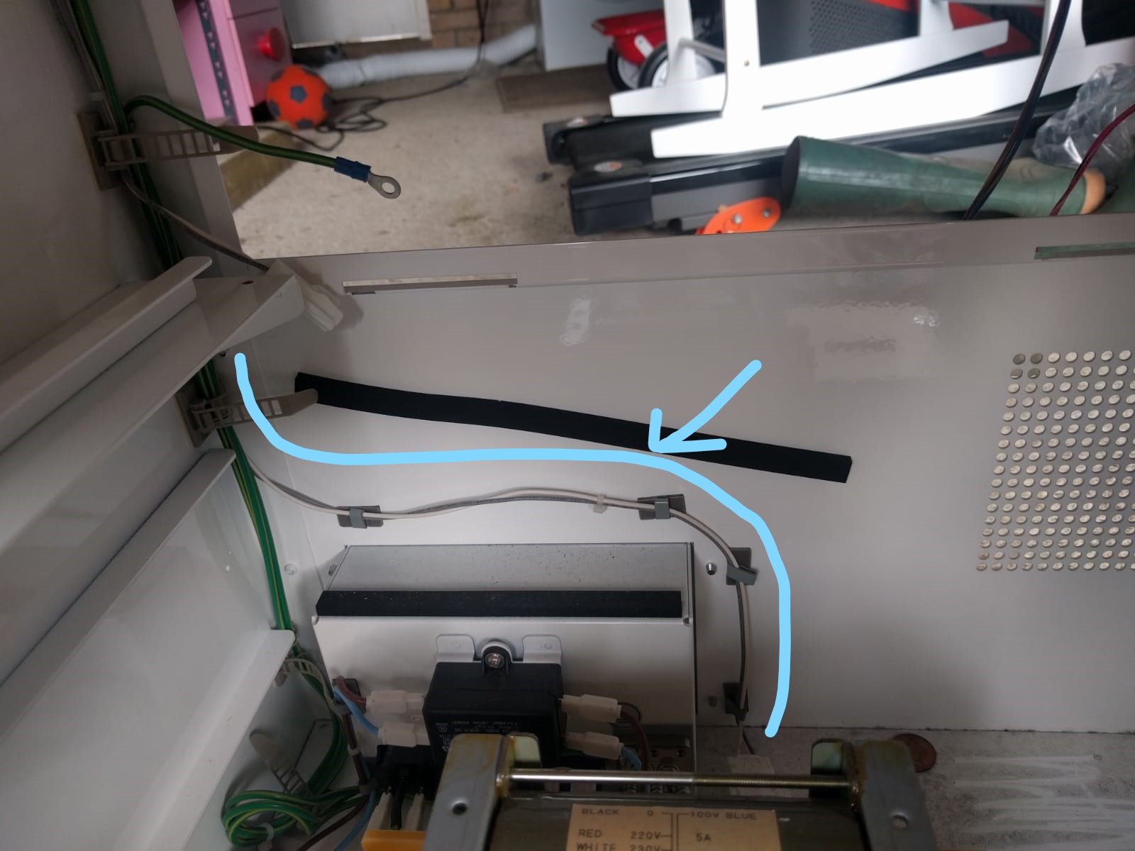
That, presumably is the power line to the monitor. All appears to join up to stuff still inside the cab. Correct?
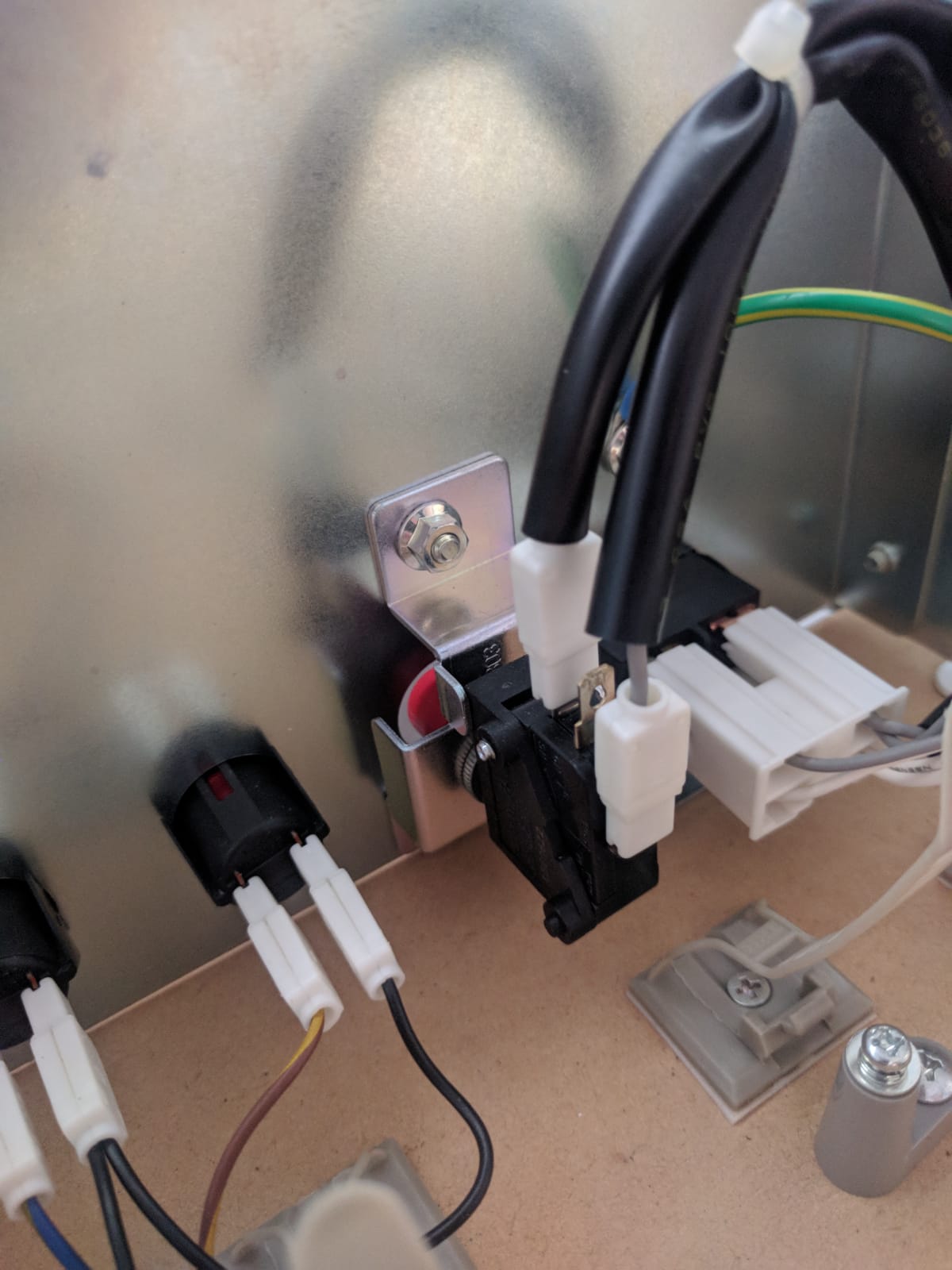
In all the excitement last night, I yoinked the connectors from the service panel. Can anyone tell me if I've put them back on the right way?
The right connector can only go grey wires up or white wires up.
The left connector has three terminals. I've got the white wire on 1 (backmost) and grey on 3 (front-most) - that is pure guesswork. I've zoomed in on Flynnster's pic above, but it's not totally clear if I've got them the right way.
This is what I have now. From Flynn's pics, it looks like the connectors on the service panel buttons can come off.
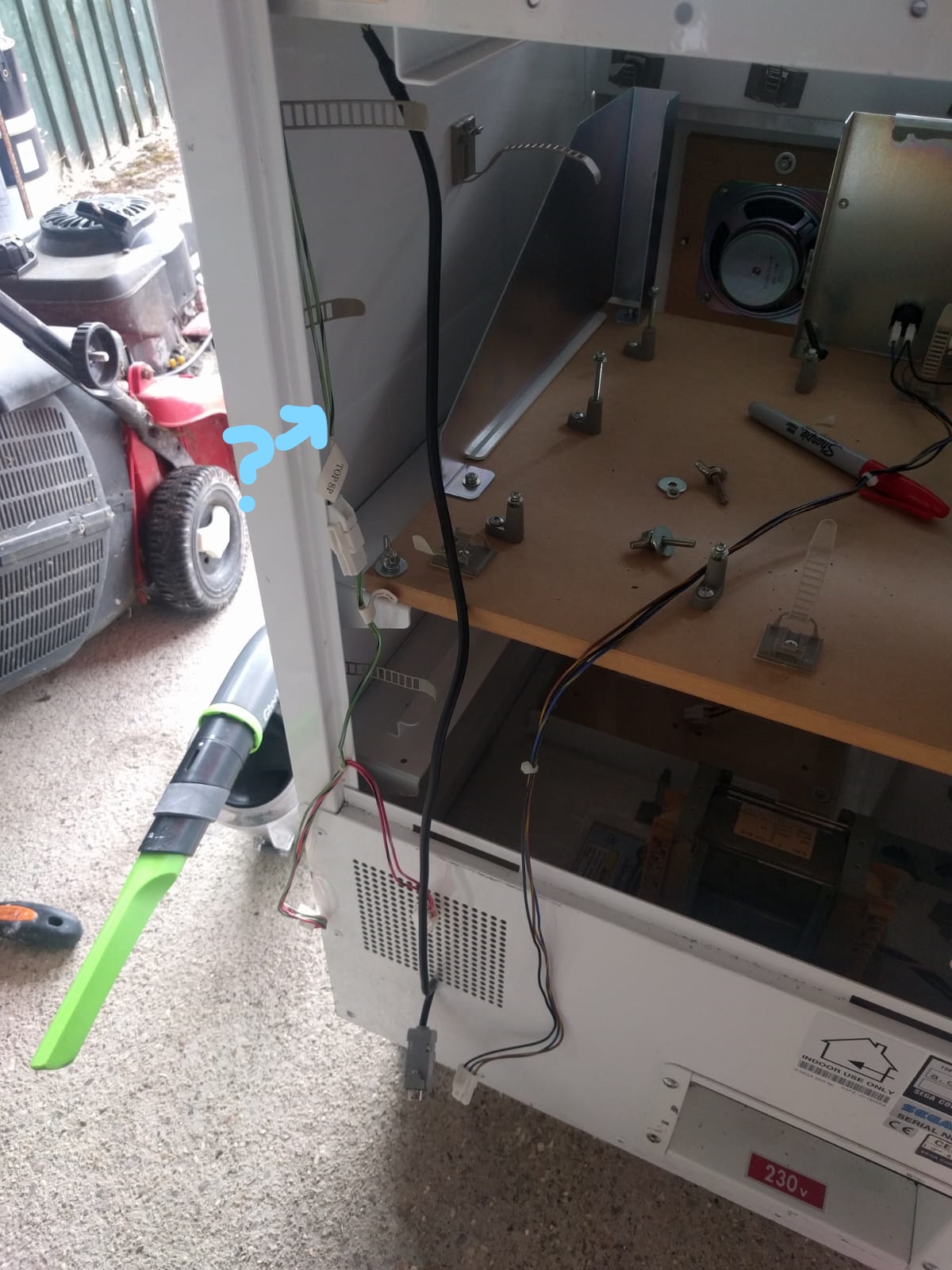
Lastly, what's are those wires labelled TOP SP on the left there? Is that anything important?
As ever, appreciate all the help. Hopefully my dumb questions help out another n00b in future

deanzor2018-08-02 09:50:06
Stuck my head in the garage before work today, and the main loom appears to be fully out now. The JAMMA loom looks a lot less scary than that beast, jeeze.
Would like to double check a few more things, if you don't mind?
That, presumably is the power line to the monitor. All appears to join up to stuff still inside the cab. Correct?
In all the excitement last night, I yoinked the connectors from the service panel. Can anyone tell me if I've put them back on the right way?
The right connector can only go grey wires up or white wires up.
The left connector has three terminals. I've got the white wire on 1 (backmost) and grey on 3 (front-most) - that is pure guesswork. I've zoomed in on Flynnster's pic above, but it's not totally clear if I've got them the right way.
This is what I have now. From Flynn's pics, it looks like the connectors on the service panel buttons can come off.
Lastly, what's are those wires labelled TOP SP on the left there? Is that anything important?
As ever, appreciate all the help. Hopefully my dumb questions help out another n00b in future
deanzor2018-08-02 09:50:06
Top SP is wiring for the speaker in the top of the bezel - dino's don't have these fitted though so it very likely goes nowhere and can be removed. The Mushi King and L&B use the top speaker from what I remember.
As Muddy said, the light green wire labelled TOP SP is a speaker wire that goes to the top of the cabinet and is not used on Dino King. You can safely remove it.
You are correct, in your first photo the grey and white wire is the one that powers the monitor (via the on/off switch).
In your second photo the blue wire needs to go onto the middle spade connector on the Demag switch. Everything else looks right. Here is a photo of mine which hasn’t been removed yet
Sooo...
Cyan wire yep - that's 110v + gnd to the monitor

Service + test button connectors - you can remove them completely, as if you are fitting a fresh jamma loom the service + test spades will just plug straight in there.
For the clips on that large degauss button, you can usually tell which way round they go based on the curvature of the insulation anyway, as it's all pretty tightly fixed in place. But erm yeah, you don't want degauss to be on constantly, so do make sure you have the terminals correct so the microswitch is in 'NORMALLY OPEN' and not 'NORMALLY CLOSED' mode!!
On off switch can be connected either way, it's just a switch.
The green labelled speaker SP wire is redundant yeah (only used on love n berry)- but I keep this in place because someday, I will do marquee lighting and I'll use this cable to connect that up (it goes to the perfect spot above the monitor)
Flinnster2018-08-02 13:57:34
Cyan wire yep - that's 110v + gnd to the monitor
Service + test button connectors - you can remove them completely, as if you are fitting a fresh jamma loom the service + test spades will just plug straight in there.
For the clips on that large degauss button, you can usually tell which way round they go based on the curvature of the insulation anyway, as it's all pretty tightly fixed in place. But erm yeah, you don't want degauss to be on constantly, so do make sure you have the terminals correct so the microswitch is in 'NORMALLY OPEN' and not 'NORMALLY CLOSED' mode!!
On off switch can be connected either way, it's just a switch.
The green labelled speaker SP wire is redundant yeah (only used on love n berry)- but I keep this in place because someday, I will do marquee lighting and I'll use this cable to connect that up (it goes to the perfect spot above the monitor)
Flinnster2018-08-02 13:57:34

Well, thanks to this thread (and a LOT of technical support from Flinnster in the DMs), my JAMMA conversion is done. Control panel from Escape-to-88 is absolutely bang on.
Next step is to Pi2Jamma it up so I can play multiple games.
Thanks fellas!
I was lucky with the condition of the cab - barely a scuff on it.
I put the art together. Because it's cartoony, it vectors up pretty nicely with minimal effort. A mate of mine printed the vinyl and wrapped the CP for me.
Still debating what to do with the side panels. That'll be about £50, so it'll be the last thing I do.
I put the art together. Because it's cartoony, it vectors up pretty nicely with minimal effort. A mate of mine printed the vinyl and wrapped the CP for me.
Still debating what to do with the side panels. That'll be about £50, so it'll be the last thing I do.

Ended up fitting a small button for the credits, small enough to mount in one of the right hand bolt holes after I'd taken the bar off the front.
Works well.
Link, in case anyone wants: https://uk.rs-online.com/web/p/push-button-switches/1035726/
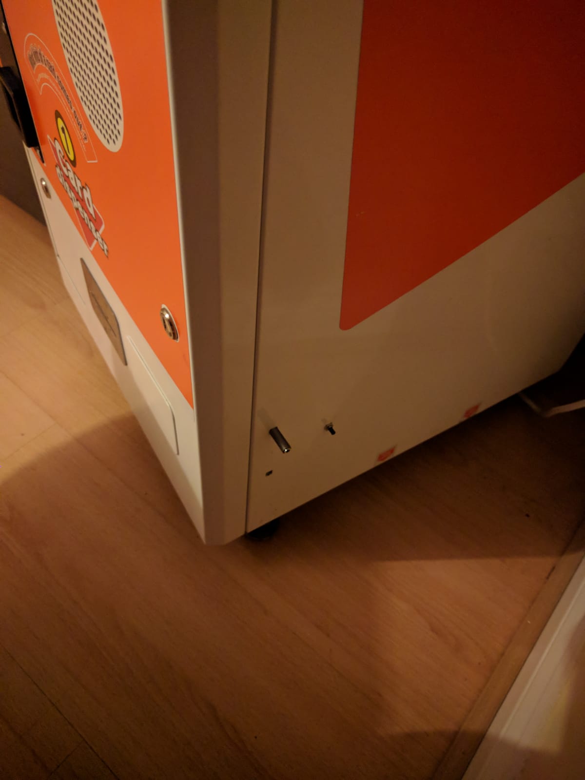
(The longer bit sticking out is to plug headphones into for now)
deanzor2018-09-28 21:43:21
Works well.
Link, in case anyone wants: https://uk.rs-online.com/web/p/push-button-switches/1035726/
(The longer bit sticking out is to plug headphones into for now)
deanzor2018-09-28 21:43:21
Hi all, I'm in the latter stages of converting a Dino King cab. There's loads of existing cables that seem to be associated with the coin mechanism and the coin counter.
I'd like them both to work fully, any idea where I connect them to my Jamma harness?
Thanks
I'd like them both to work fully, any idea where I connect them to my Jamma harness?
Thanks
Hi tronbaby,
Firstly, the coin door wiring remains untouched so no need to worry about that.
The wiring between the coin door and the machine is connected via an 8-way JST connector. The door connector is a plug, the machine connector is a socket.
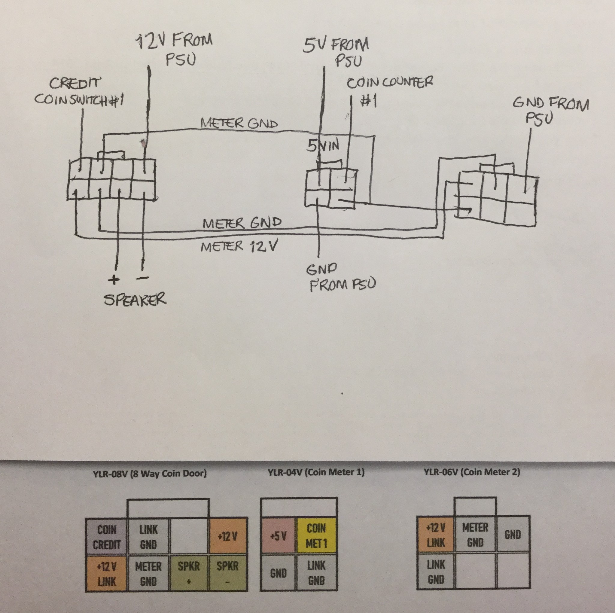
Looking at the 8-way JST connector socket (the connector on the machine side) viewed from the front, the wiring is as follows:-
Top row from left to right:-
1. Credit Switch (wire to JAMMA pin 16 - Coin Switch #1, Parts side)
2. Meter Ground Link (wired to bottom right 4-way socket of Meter #1 and wired to bottom left of 6-way socket of Meter #2)
3. (Not used)
4. 12v (wire direct to power supply switcher)
Bottom Row:-
5. 12v Meter Link (wired to top left of 6-way socket of Meter #2)
6. Meter Ground (wired to top middle of 6-way socket of Meter #2)
7. Speaker + (wire to JAMMA pin 10, Parts side)
8. Speaker - (wire to JAMMA pin L, Solder side)
[sub][/sub][sup][/sup]
For Meter #1 (5V) 4-way JST connector socket (the connector on the machine side just behind the cash box) viewed from the front, the wiring is as follows:-
Top left: 5v (wire direct to power supply switcher)
Top Right: Coin Meter (wire to JAMMA pin 8 - Coin Counter #1, Parts side)
Bottom left: Ground (wire direct to power supply switcher)
Bottom right: Meter Ground Link (wired to pin 2 of 8-way door connector and to bottom left pin of 6-way socket of Meter #2)
For Meter #2 (12V) 6-way JST connector socket (the connector on the machine side just behind the cash box) viewed from the front, the wiring is as follows:-
Top left: 12v Meter Link (wired to pin 5 of 8-way door connector)
Top middle: Meter Ground Link (wired to pin 6 of 8-way door connector)
Top Right: Ground (wire direct to power supply switcher)
Bottom left: Meter Ground Link (wired to pin 2 of 8-way door connector and to bottom right pin of 4-way socket of Meter #1)
Bottom Middle: (Not used)
Bottom Right: (Not used)
Below is a picture of my diagram I used when wired mine which might help to explain things:-
Firstly, the coin door wiring remains untouched so no need to worry about that.
The wiring between the coin door and the machine is connected via an 8-way JST connector. The door connector is a plug, the machine connector is a socket.
Looking at the 8-way JST connector socket (the connector on the machine side) viewed from the front, the wiring is as follows:-
Top row from left to right:-
1. Credit Switch (wire to JAMMA pin 16 - Coin Switch #1, Parts side)
2. Meter Ground Link (wired to bottom right 4-way socket of Meter #1 and wired to bottom left of 6-way socket of Meter #2)
3. (Not used)
4. 12v (wire direct to power supply switcher)
Bottom Row:-
5. 12v Meter Link (wired to top left of 6-way socket of Meter #2)
6. Meter Ground (wired to top middle of 6-way socket of Meter #2)
7. Speaker + (wire to JAMMA pin 10, Parts side)
8. Speaker - (wire to JAMMA pin L, Solder side)
[sub][/sub][sup][/sup]
For Meter #1 (5V) 4-way JST connector socket (the connector on the machine side just behind the cash box) viewed from the front, the wiring is as follows:-
Top left: 5v (wire direct to power supply switcher)
Top Right: Coin Meter (wire to JAMMA pin 8 - Coin Counter #1, Parts side)
Bottom left: Ground (wire direct to power supply switcher)
Bottom right: Meter Ground Link (wired to pin 2 of 8-way door connector and to bottom left pin of 6-way socket of Meter #2)
For Meter #2 (12V) 6-way JST connector socket (the connector on the machine side just behind the cash box) viewed from the front, the wiring is as follows:-
Top left: 12v Meter Link (wired to pin 5 of 8-way door connector)
Top middle: Meter Ground Link (wired to pin 6 of 8-way door connector)
Top Right: Ground (wire direct to power supply switcher)
Bottom left: Meter Ground Link (wired to pin 2 of 8-way door connector and to bottom right pin of 4-way socket of Meter #1)
Bottom Middle: (Not used)
Bottom Right: (Not used)
Below is a picture of my diagram I used when wired mine which might help to explain things:-
