Initial D - Wiring Questions

jww

User
vacBacker
Feedback
4 (100%)
Credits
46CR
Hiya,

Please can a kind soul help advise me about the following wiring questions that I've got?

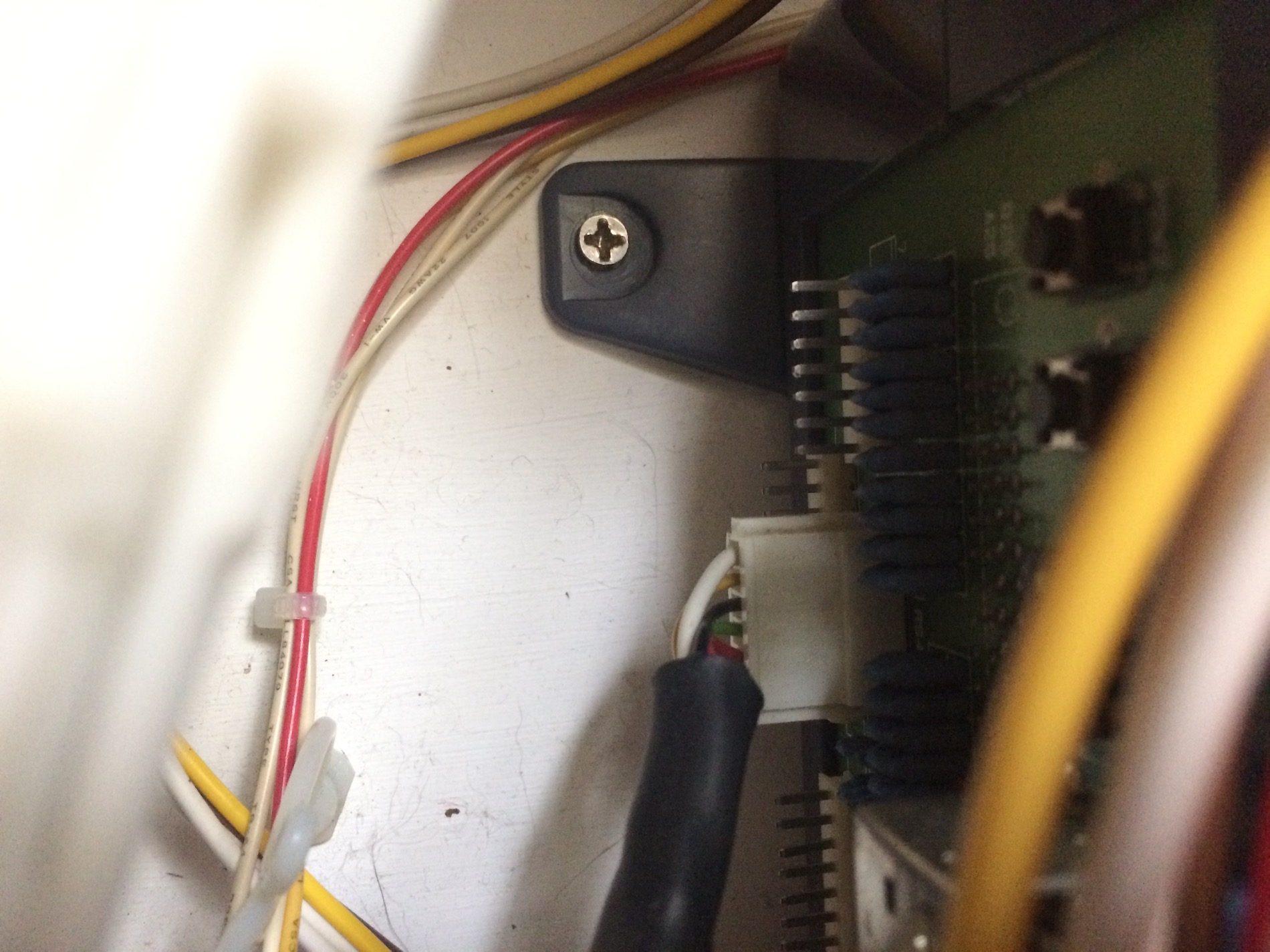
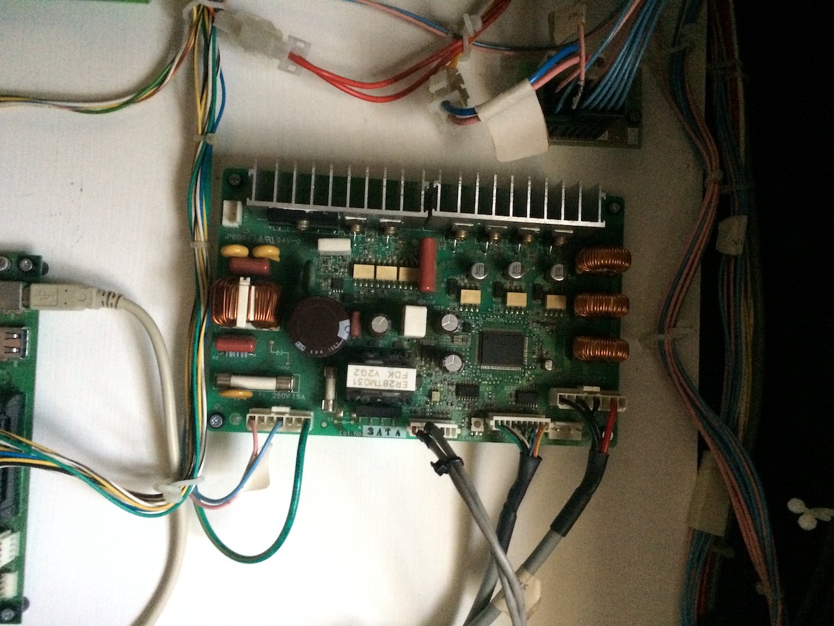
1. I seem to be completely missing the wire from Naomi (cn9) to 838-14174 (cn2)

- I'm assuming I need this cable
- Any idea where I could pick one up and what should I search for as have no idea what the part number of cable would be

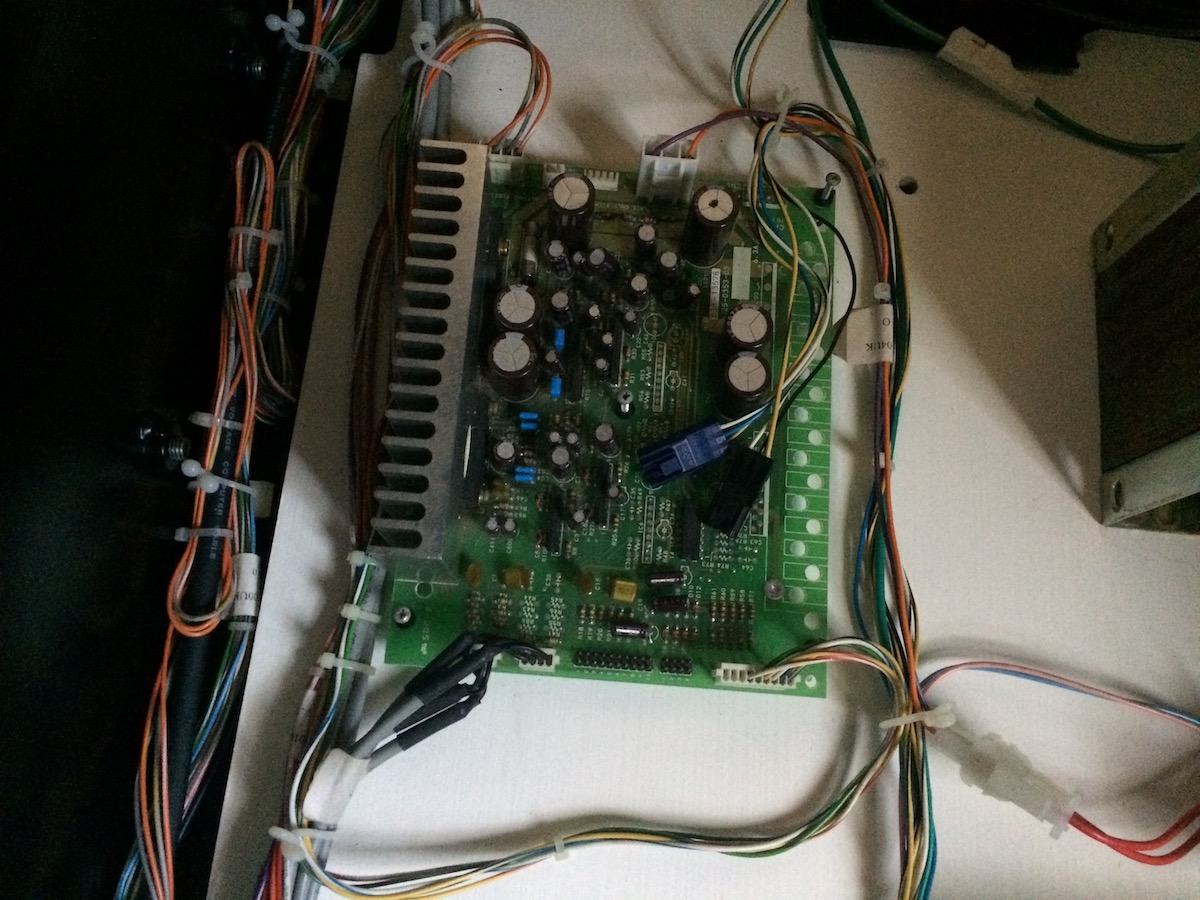
(Relevant Pictures of my invisible cable below)
smiley1.gif


IMG_0882.jpg


IMG_0883.jpg


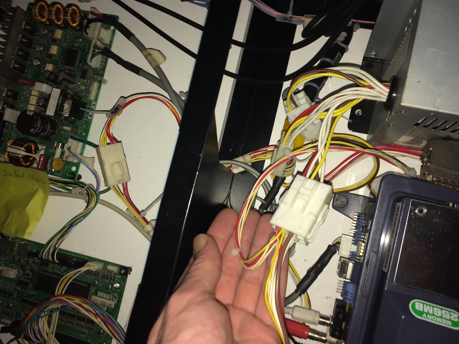
2. Naomi (CN1) - Should the cable that connects into CN1 be a straight cable or a Y-Splitter?

(I'm going to struggle to explain this as I'm stupid, please bear with me)

My cab came with a y splitter in the cab, and as i've been restoring the cab, and connecting things up and adding hardware that it didn't come with (naomi2 etc), i'm at a loss as to if this is the correct cable to use/have.

One end of the y splitter connects/fits into the naomi2, port cn1 and one of the other ends fits into the psu. That makes sense to me, naomi needs power right...

But I cannot for the life of me, what else should plug into the spare end of the Y splitter. Either I'm blind and not seeing the cable to connect in, or am I missing a cable to plug into this?

OR - should this y-splitter not be in my cab - and it should be a straight cable instead?

My cab did come with a separate bag of spare/extra wires, and one of them is a cable that I could also use to connect naomi to power instead of the y-cable that i found inside the cab (hence assuming i'm supposed to use it).

So, in short, I dont know if I should replace the y-cable with the straight cable or what. Please help as I'm horrifically confused.
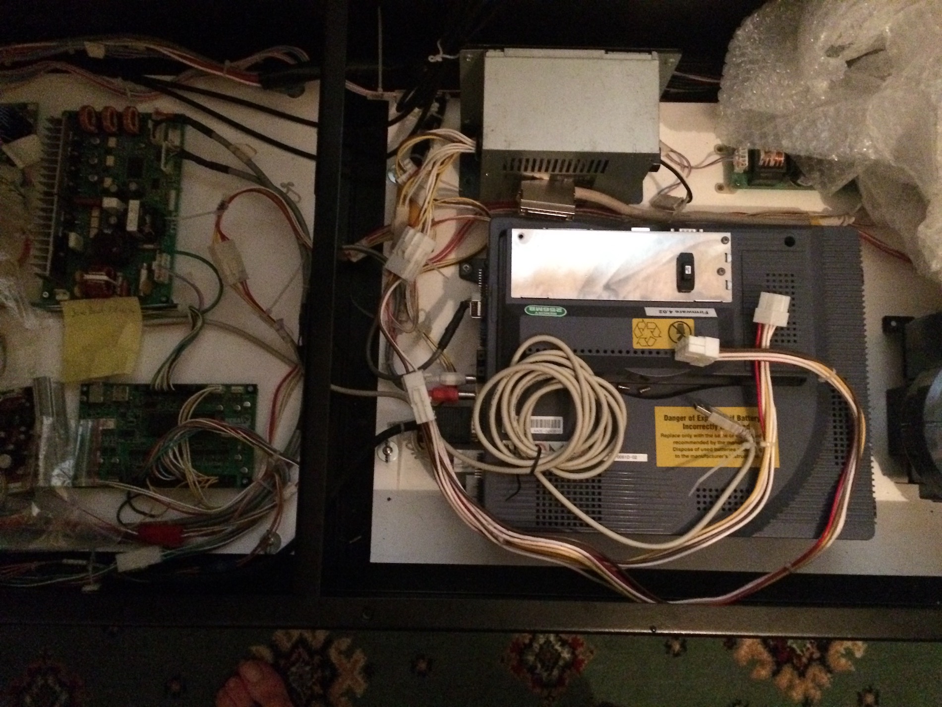
IMG_0874.jpg


IMG_0875.jpg


IMG_0876.jpg


Any help would be appreciated as I'm very lost and know that I'm close to first power-on of my cab, but worried to death, as i've taken painstaking care over the last 5 years to restore the cab to this point, I don't want to cheb it up now.

Thanks loads in advance for any advice

Cheers,

Johnny
 

Outrun2

Colonel Outrun
Feedback
5 (100%)
Credits
1,182CR
1. I seem to be completely missing the wire from Naomi (cn9) to 838-14174 (cn2)

This is the midi servo drive board cable. You can play the game without it, but you won't get any force feedback through the steering wheel.

2. Naomi (CN1) - Should the cable that connects into CN1 be a straight cable or a Y-Splitter?

You should have an 8 way and a 6 way power plug that comes from the PSU to the Naomi. The 8 way has red/brown/yellow/white, wheres the 6 way has just brown/yellow/white.

It looks like you have the 6 way plugged in already so that's fine. Is the 8 way loom split into two 8 way plugs - is this the Y-splitter you mention? If so, you only need one that goes in next to the 6 way already plugged in. The other is not required. Sometimes this loom is split, but with a different connector that goes to the GD-ROM drive - I think I can see you have the GD-ROM drive connector plugged in - I assume this cable comes from the Naomi as this is the other option.

From what I can see you are ok, just need a drive board cable to get the FFB working - I might have a spare, I'll check when I can get to the garage.

Great work so far
smiley20.gif
 

jww

User
vacBacker
Feedback
4 (100%)
Credits
46CR
Hiya Outrun2,

Thank you for coming to my rescue, I really appreciate it. I'd got so worried about trying to understand the y-splitter as well as wondering if there was a missing cable.

Will put up a wanted posted for that cable as looking forward to force feedback.

Yes, you got it right, I was (badly) talking about the 8 pin plugs (unconnected in the photos). Fortunately I got box of spares with the cab and there was a straight 8-8 cable in there. Discarding the y-splitter, I've connected it up now as well as a load of other wires connected and work done too, so it's been a very productive weekend - woo hoo :)

Am thinking that I'll update this thread with photos and video before first power on, just to get things checked, as worried that I'll blow it up so close to the end.

Thanks again for all your help.

Cheers,

Johnny
 

Vamino

Insert coin(s)
vacBacker
Feedback
23 (100%)
Credits
2,700CR
Good going so far mate.
smiley20.gif


I'm looking forward to seeing the photos before the big power on!

Initial D is such a great looking cab in my opinion. I sold my cab last year and I miss it so much that I'll be building my own once I've cleared a backlog of projects. I've been buying parts like a nutter since last year so it should hopefully come out pretty decent.
smiley1.gif
 

jww

User
vacBacker
Feedback
4 (100%)
Credits
46CR
Ok, I think I'm nearly ready to think about powering on my ID1 cab for the first time so would very much appreciate it if anyone with the knowledge could check that I've done the wiring correctly.

Additionally I've got 2 monitors and as they're so big, I'd like to test them outside of the cabinet, to find the best one, before fitting the winner to the cab.

NB1: I haven't plugged the 2 cables into the monitor yet but this will be done at the last moment. (To do so requires moving the cab to meet the monitor on the table, which blocks the door)

NB2: I've found a loose wire (with pin) near one of the psu/transformer things. I haven't looked further yet, as to what it's from and if it can be fixed easily. One of my missions this evening is reading the wiring diagram again and trying to find which one it is, and looking closely to see why it's come out of the molexy-connector with it's pin. If I get stuck I'll post in this thread asking for help. I won't power on the cab until I've solved this problem and will post seperately about it, so just mentioning that you can feel free to ignore this as part of the wiring check.

Video Overview:


Pictures:

Natch, please ask if you want to see more pix of a specific area.

IMG_1072.jpg


IMG_1082.jpg


IMG_1086.jpg


IMG_1088.jpg


IMG_1089.jpg


IMG_1090.jpg


IMG_1091.jpg


IMG_1093.jpg


IMG_1094.jpg


IMG_1096.jpg


IMG_1097.jpg


IMG_1098.jpg


IMG_1099.jpg


IMG_1100.jpg


IMG_1101.jpg


IMG_1102.jpg


IMG_1103.jpg


IMG_1104.jpg


IMG_1108.jpg


Image below: Anyone know where this 6-pin connects to? It comes from the baseunit and I haven't been able to work out what (if anything) connects to it yet.

IMG_1110.jpg


IMG_1120.jpg


IMG_1121.jpg


IMG_1122.jpg


Cheers,

Johnny
 

terminator2k2

Active member
Feedback
1 (100%)
Credits
327CR
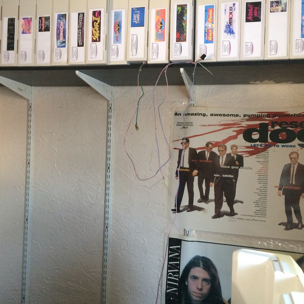
The 6 pin connector with the pink and blue wires are as a guess the 100v feeds for the dash fan, monitor power and topper illumination feed...

in your last pic with loom on the shelf by the game boxes, is that black connector a 6 pin?
terminator2k22017-08-27 20:49:30
 
  • Like
Reactions: jww

jww

User
vacBacker
Feedback
4 (100%)
Credits
46CR
terminator2k2 said:
The 6 pin connector with the pink and blue wires are as a guess the 100v feeds for the dash fan, monitor power and topper illumination feed...

in your last pic with loom on the shelf by the game boxes, is that black connector a 6 pin?

Hiya and thanks for the advice, I appreciate it a lot.
smiley32.gif


Ah yes, the old 'its behind you' trick. I completely missed that, and misread my own labels, hence hanging them up as I thought they all went in the topbox. Doh. It checks out, thank you, thats another mystery resolved.

Ok, now to see what everyone thinks to the overall wiring before getting the collective nod to turn it on (loose cable being worked on separately and will be resolved before power on).

Cheers,

Johnny
 

terminator2k2

Active member
Feedback
1 (100%)
Credits
327CR
That loose pink wire needs to go in the power distribution block.....

which one i cant say as the pics arent that clear.....but i think you should be able to sort that 1.....

everything looks good to me so far......
 
  • Like
Reactions: jww

jww

User
vacBacker
Feedback
4 (100%)
Credits
46CR
Hello all, here's a bit of an update:

First power on was last night and nothing caught fire, exploded or anything! :) Can't tell you how happy I am. This resto has been in the making for years. I totally expected that there'd be many issues to resolve after power on, I just didn't want it to explode on first power on, so was very happy that it didn't.

# First power on:

* Noticed monitor is green
* Hear Naomi jingle and see message "error 34 gateway not found"

Read up a bit and learn that the netdimm is set to booting over network mode. I am interested in this functionality, but for now want to keep things vanilla and simple and boot off my gdroms.

IMG_1142.jpg


Set netdim jumpers to gd-rom mode and check monitor d-connector is correctly plugged in and has no bent pins etc.

# Second power on:

* Monitor still green
* get message "error 26 option board malfunctioning"

Read up a bit, seems that error is caused by incorrect security chip, bad fitting of chip or bad netdim seating or bad netdim board. Investigate my chip, it's for the wrong game. doh.

Fix incorrect security chip by removing it and plugging in an ID1 chip
smiley9.gif


# Third power on:

* Monitor still green
* get message "card r/w error"

Read up a bit, cant face card reader issues atm, so go into test mode and disable card reader.

# Fourth power on:

* Monitor still green
* No more error messages, game loads into ram/netdim, see naomi jingle screen again, then it goes black with nothing else.

nb: control panel is not connected to cab yet, nor is lightbox.

Since then, I've tried to focus on why monitor output is largely green.

I believe that I have a sanwa 29es31 which is a 31khz monitor and understand that initial-d/naomi2 should be set to 31khz mode on the naomi2. From reading, it appears that the monitor should auto detect the 31khz mode, so no dip switches on that, but there are dip switches I need to set on the naomi.

Atm, all dip switches are off and the game loads from gd into ram, the screen goes black and stays like that. I wondered if the green output was because i'd got my board in the wrong mode (15khz rather than 31khz).

From reading this link https://wiki.arcadeotaku.com/w/Sega_NAOMI_Error_Codes, it seems to say that i need to put dip switch 1 to on position, on the naomi. I tried that but then got a garbled caution 53 message saying i was in wrong display mode

IMG_1154.jpg


IMG_1152.jpg


...so put it back again. I think that link may be for naomi1 motherboard, as the naomi gd-rom manual seems to suggest dip switch 1 must be off for 31khz mode.

Dip 1 set back to off and i can read the screen clearly again, albeit in green:

IMG_1149.jpg


Oh well, at least I've ruled out wrong khz mode.

So that's where I'm up to at present, cant believe how much progress I've made, this is fantastic. Really getting there now!

Gonna read up some more and re-check my photos to see if I've connected anything up wrong.

My current thoughts about the monitor issue and game not finishing booting are:

* I attached chassis to monitor incorrectly
* I connected some other cables up incorrectly in cab
* Bad video cable
* Game needs control panel connected up to boot further than it does
* Bad tube
* Try my id2/3 games

I ideally wanna get the monitor displaying a clean picture before going too much further, as once that's sorted, I can mount the monitor in the cab and have easier access to all the other things that need attention.

Anyhow, I've got some reading to do before bed, better head off now, but wanted to give an update on my progress.

Cheers,

Johnny
 

Vamino

Insert coin(s)
vacBacker
Feedback
23 (100%)
Credits
2,700CR
I missed this post, I thought your last post was asking for wiring help.

Nice one mate.
smiley20.gif


It's booting up, that's a start!

Once it loads the game then it should get to the card reader and drive board initialisation messages. It shouldn't go black from my memory. When you go into the service menu does it say Initial D as the game? Have you done a net dimm test in the service menu?

My memory is a bit hazy as I haven't had one for about a year now.
But, hopefully someone else can chime in and help with the issue you are having.

As for the screen, I've had nothing but problems with those Sanwa monitors. Have you tried tweaking the pots on the chassis? There should be one each for Red/Green/Blue. Best to see if someone else has some proper advice.

Well done for getting this far though, the end is in sight!!
smiley1.gif


Cheers.
 
  • Like
Reactions: jww

robotech

Active member
vacBacker
Feedback
4 (100%)
Credits
823CR
looking good so far
smiley20.gif


the boot sequence on my cab is

naomi checks memory up to 100% followed by a black screen

naomi loads game upto 100% then black screen again

naomi checks memory again upto 100%
then a black screen with text about initialising card reader ( card reader makes diskreading noise )

then a black screen with text about initialising steering and moves the steering wheel

then the game starts

yours might be hanging on the black screen because its looking for the ffb motor which is not connected

try plugging your Naomi 2 into a pc monitor to see if its outputting correctly

I can only echo what others have said about those crappy sanwa monitors
I have not seen a nice one yet
 
  • Like
Reactions: jww

jww

User
vacBacker
Feedback
4 (100%)
Credits
46CR
Hello Vamino and Robotech,

Thank you both for your advice and sorry for the delay. There were a few issues happening at once. After I had a cuppa and a think, I tried my ID2 game+chip instead and the game started right up! So, I got an issue with my ID1 disc I guess so will try cleaning that once I get chance.

I've got 2 of these monitors + chassis, so have been swapping things around and now have it working in colour - woo woo! Gunblade has been very kind to give me advice. Out of the 2 tubes, I didn't want to use this one thats installed now as it has some scratches and screen burn, but I'm very happy to have a working solution and it's not that visible when the game is running.

Given time in the future, I'll re-test the spare tube + chassis and see if I can't coax it to life. For now tho, that can wait.

I've not finished the resto yet, plenty more to go: the card-reader is showing no signs of life, artwork needs to be applied, I want to rebuild the control panel and I'm curently trying to work out what magic socket I need to remove the shifter plate, but it's all good, very enjoyable and rewarding.

I've put some little videos on youtube, here's the first time I got a game to load with colour :)


Here's a few pictures of the cab recently:

IMG_1194.jpg


IMG_1196.jpg


IMG_1197.jpg


Since then I've fitted the control panel again and have done most of the wiring routing, not too much more to do.

Am going to run through the naomi tests with everything connected today and hopefully have my first go on the cab :) Woooooooo

I think if I have any other q's, I'll create a snagging-list thread in the tech section, but will try to solve the remaining issues myself if possible. Very happy with how things are going and thank you again everyone who has helped and offered advice.
smiley32.gif


Cheers,

Johnny
 

Outrun2

Colonel Outrun
Feedback
5 (100%)
Credits
1,182CR
Very nice work mate - not sure how I missed your last updates, but glad you got some help from the other guys.

Cab is looking great - I must say re-powdering the grey on the frame and doing the speaker brackets is going that extra mile that only a few venture out to! You take a while on your cabs but you are thorough and enjoy the ride, that's good stuff in my book
smiley14.gif


Regarding the monitor, you know you can swap the good chassis onto the nicer tube if you wanted to in order to get the best combination. If you haven't done it before though, don't just tear into it (as if you would!), but read up on the things to take care over and follow the recommendations on discharging the tube first.

Strange one about the iD1 disc/chip - if the chip was accepted and the game loaded into the dimm it should work ok. Have you tried loading iD1 again since as it may work now - sometimes the dimm needs a good firm press down to be completely happy and pressing in the iD2 chip may have inadvertently done this. Just something to consider..

With the card R/W error - have you tried entering the test menu and doing a test on it? You can run a cleaning function which can help (even if you don't have a proper cleaning card - just put a normal game card in).

As for the socket needed for the shifter plate, it should just be a security torx - you can pick up a nice set of tamperproof bits from many places but this is a good example.. no need to spend any more..

https://www.toolstation.com/shop/p92461?mkwid=sc7yFVkNJ_dc&pcrid=142481253537&pkw=&pmt=&product=92461&gclid=EAIaIQobChMItdjkvLKY1gIV7rztCh2f

Once again, congratulations on a terrific resto so far
smiley20.gif
 

jww

User
vacBacker
Feedback
4 (100%)
Credits
46CR
Hiya,

Sorry for the delay, completely missed your reply, I really appologise for being slack and not paying enough attention to my online stuff.
smiley19.gif


Thanks for your awesome help and kind complements. This has been a really difficult project.

# Monitor

Thanks for the chassis swap advice and important discharging warning mate. Yeah, I heeded that advice when I got into the hobby and got a high voltage discharge probe and always use it before going near any of monitors. Now I always go through the process even on monitors that auto discharge, just to be sure.

My resto has hit a stumbling block, the monitor packed in imediately after installing it. Out of the 2 tubes and chassis I managed to get one working and tested on the bench prior to fitting to cab, it had a great picture so updated my youtube channel and was super happy.

Switched everything off, unplugged, lifted crt into cab, reconnected, now either get no picture or scary as hell sounds which sound like it's trying to summon Hades, divide by zero and go to silicoln heaven. Lifting it in to the cab nearly killed me in itself. What the hell do crt's have inside them? Feels like bowling balls and crates of Skol
smiley36.gif


I've tried both tubes, all chassis combinations and can't get a working monitor out of them now. Only scary as hell sounds. After reading on the net other peoples experience with these models of crt's, I'm not going to go any futher with them. I had both chassis serviced but I suspect they are just a bit rubbish and dying and don't want to put any more money into them. Everyone else who mentions them on the 'net seems to hate them and can see why now.

So yeah, am "this close" to finishing the cab and still haven't been able to have a go on it! It's heart breaking and frustrating but totally part of the hobby.

At the mo have got an old little pc lcd sat to the side of the cab on a chair to the side, just so I can do some bits of resto/use bios to test/calibrate the rest of the cab. Have got a wanted post on the forum now for a crt, hopefully can get a non sanwa crt soon as I'm off work this week and next so actually have some time to do things on the cab.

# RE: Not booting up everytime:

I've put id3 in the cab atm and am servicing all fans as they are way too loud. This is booting up consistently now, so I dunno if its my id1 game disk, or some of the other servicing/battery replacing has fixed that issue but I'm keeping id3 in there so I can test the various bits n bobs that I'm working on.

# Card reader

Thanks for the tip about disabling the card-reader, yes, I've found that now and have to do that as otherwise cab will not boot. Have seen the bios test settings and will investigate those more when I get more time. Now I've replaced the cr2032 battery for the naomi, it is keeping the settings now, which it wasnt before, which had me stumped for a bit
smiley36.gif
Am wondering if that was part of my issue.

# Gear shifter

Anyhow, changing topic to gear shifter, I think someone (Operator?) has fitted different bits to the gear shifter as I've got that torx bit set that you linked to but none of the bits fit the screws used in mine. (Unless I'm being an idiot)

Here's a pic of my shifter and set:

IMG_1257.jpg


IMG_1256.jpg


So there you go, thats current status, nearly there now. Am off to big diy store a few miles away tomorrow to see if they have a bit that will fit that strange screw and then hopefully after a bit of cleaning/servicing, that'll be the control panel completely sorted.

Thanks again for your kind message with help and advice.

Cheers,

Johnny
 

jww

User
vacBacker
Feedback
4 (100%)
Credits
46CR
Heya,

Quick update:

Got the shifter strange bolts removed. I think they might be 'external torx' but before made anymore headway into looking up what they were, I got them unbolted! After looking at it with the lower shifter cover removed, was able to grab the bolt from underneath with a pair of pliers and turn them loose that way.

IMG_1270.jpg


IMG_1272-2.jpg


They look to be 25mm M5 bolts, I think the originals are the regular star shaped torx with the center pin - can anyone confirm?

Cheers,

Johnny
 
Top