loose jamma harness 101

Lastspaceship

Active member
vacBacker
Feedback
3 (100%)
Credits
198CR
prob basic question but looks like a loose connection on my jamma harness, went through the pins but just getting expert eye on which it likely is. Wondering whether i should replace to tidy up at some point..

loosejammaharness.jpg
 

qjuk

Active member
vacBacker
Feedback
47 (98%)
Credits
1,656CR
First of all you need to trace back where that loose wire is going to. Power off the machine and ideally use a multimeter set on continuity check to see where the other end is connected to. It looks as if it might be a +5v wire as it seems the same colour and length as the other +5v wires. However, don’t take my word for it and you’ll need to check for certain incase you damage anything by wiring it up incorrectly.

It’s a shame that the Ground wires are not the standard black and +5v not the standard red colours. If it was me, I’d be rewiring that whole connector and using heat shrink tubing on every connection. At the very least, I’d be using black heat shrink for the ground and red heat shrink for the +5v to help identify the voltages.
 

Shagster

Newbie
Credits
28CR
Don't replace if there isn't any heavily tarnished or corroded pins. If only a couple are damaged, you could just change them out with unused pins. It's a good quality, gold plated connector. Unlike all of the cheap chinese ones flying about.

You could just clean the pins with isopropyl alcohol and an old tooth brush. Cardboard is another way of cleaning them. Don't use a heavy abrasive, like sand paper. Which takes the gold protective layer away and leaves the pins open to quickly oxidize.

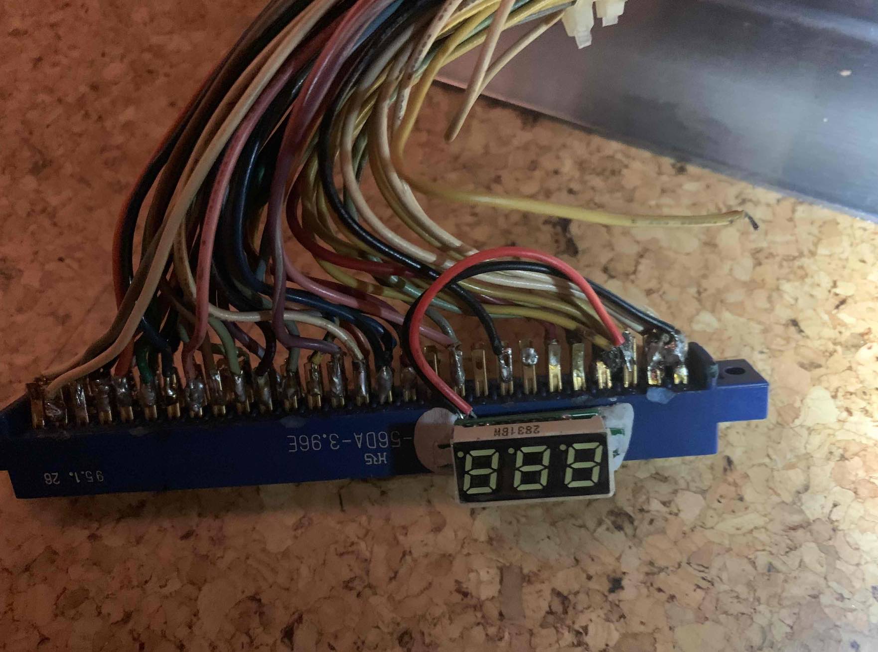
It's the decent gold plating on these, that make them worth keeping. Think there around 4 or 5 quid new, not expensive. But why replace something that doesn't need replacing, right.

Get yourself some 60/40 leaded solder and some flux. Just incase you're having any issues with the solder not taking. Then just cut back 10 or 20 mm on each wire, tin the wires and the connector tabs. Solder them together. Stick some heatshrink tubing on before you solder everything, obviously, and away you go. It'll then hopefully work and look better than new
smiley1.gif
 

Lastspaceship

Active member
vacBacker
Feedback
3 (100%)
Credits
198CR
Traced this back with a multimeter as suggested, it was +5v. Bit ashamed to say haven’t done the full fix will loop back to that !!! for now soldered back into the 5v pin all working. (Bit tricky plenty of wires into the 5v area . Thanks again
 
Top