NOTE: This repair log uses my Slice tester mentioned in the post SLICE with the addition of an extra cable that expands its capability to 32 pin devices. At the moment this cable is not available for sale but it will be soon.
Was asked to look at this board for a friend. On visual inspection I noticed that C203 a 12v cap near the edge connector had been hit hard and badly damaged. With this cap bad the M82 board will create significant display glitches and audio clicking. I replaced this and the display glitches and audio distortion went away, unfortunately I forgot to take a picture!
Next up was the usual ROM verify checks using a Mame rom set and my eprom programmer. I also checked the rom sockets were clean and not corroded as I have certainly had this cause issues in the past on M82's.
At this point I would get the usual static screen when booting the board, but thats just about as far as it would get, though after a short delay it would randomly change the gfx or colours slightly.

First thing was to use my logic probe as a quick way of checking to see that the board was running. Pin 21 (Reset) of the NEC CPU was high on boot up then stayed low and Pin 22 (Ready) was pulsing so I knew the CPU was running and the board was not watch dogging. I also then quickly ran over one of the program rom (IC52) address and data lines and saw plenty of activity.
So I knew the board was starting ok but getting stuck somewhere during the initialisation. So I hooked Slice up to IC51 (1Mb ROM), which I knew from Mame source module M72.cpp was mapped into $40001-$7FFFF & $C0001-$FFFFF. Its a 16 bit system so IC51 is loaded into each odd byte in this range and IC59 (1Mb ROM) is loaded into the even bytes. Running Mame in debug mode then enables me to see what code is being executed at the locations that Slice reports as being accessed.

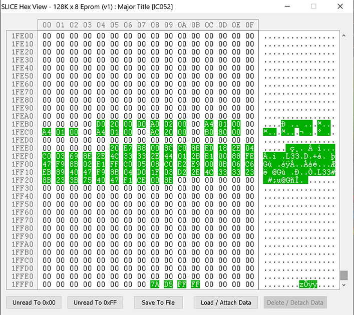
The bytes at $1FFF8-$1FFFB is the startup branch instruction that is executed at $FFFF0 as this ROM is also mapped into upper memory.
The block of green bytes starting at $1FEE5 is the actual code execution start address ($1FEE5 * 2 = $3FDCA + $40000 = $7FDCA) which is confirmed by Mame debug if you single step the initial branch instruction.
This initial block of code reads from a table of ram locations & sizes doing memory checks. The table bytes read are shown at $1FEB4-$1FECE.
But I know this table has a few more entries. These have not been read in the above sample at Slice's maximum time is 300ms and these ram tests take a bit longer to execute. So checking the code I see that once the table has been finished the code jumps to $7FE50 where it sets up the stack and starts ROM checks. So I decided to setup some address line triggers to start the 300ms sampling when $7FE58 is accessed after the initial ram checks are completed. So I convert the address, $7FE58 - $40000 = $3FE58 / 2 = $1FF2C. Which means A16 - A8, A5, A3, A2 will be high with the rest low.


As can be seen by the green bytes, $7FE58 is executed which leads to the CALL to $7FE8B which does the first 2 ROM checks. The RET instuction is hit but the code at $7FE60 (offset $1FF30) is not being executed. This makes me think work ram as the stack has just been setup and is crucial for a CALL/RET to work correctly. I then modified the address line triggers to $1FF30 and found as expected that Slice did not get triggered.
So I swapped to a narrow 28 pin clip and checked the two work rams at IC50 & IC58.


IC50 passed with no errors, but as can be seen IC58 was shown as faulty. So the second fault was identified and the ram was replaced with high hopes of a working board......
Instead of initial pause then the screen clearing and RAM/ROM OK messages appearing, I just got a blank screen!
So I decided to go back to checking the ROM to see where the code was getting stuck at now. From looking at Mame debug I knew that after the initial code at the end of the ROM memory was executed it would jump to $400 in the lower ROMs (IC52 & IC60).
As I already knew that this ROM was being checked I wouldn't be able to setup a set of address triggers, so I settled for just booting the board, waiting for the black screen and starting a sample.

This showed me that the code at $4c0 was being executed, which when checking in Mame was just looping back on itself. Setting a break point in Mame proved the code should be getting here but then an interrupt is triggered (vector 32) and the code at $4E7 should be executed. So I knew interrupts were not being generated.
On a M82 interrupts are handled by two NEC chips (uPD71059 & uPD71088). Without doing any more checks I decided on the 71059 being an Interrupt controller so I removed the IC and replaced it with a known good one.
No change! So even though Slice does not directly check uPD71088's I was able to use the DIP20+ type to check activity between a working board and this faulty one.
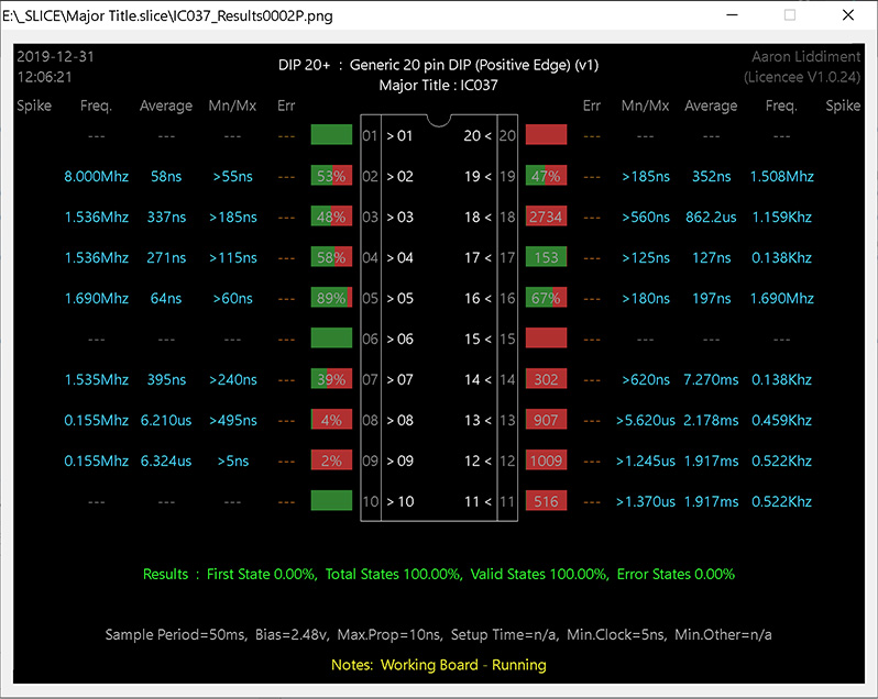
So that gave me a baseline for what I should be getting. When using Slice I normally use the Float check option to check I have good clip connection to the pins. On the faulty M82 board I was getting 2 pins indicated as floating even after re-positioning the clip a few times they still reported as being floating. They had been fine on the working board. So straight away I knew this IC had issues. When checking the datasheet I noted that both were outputs and connected with interrupts!


So I replaced IC37 and this time the board continued after blanking the screen to display RAM/ROM OK and carry on to run the game.
HOWEVER, I then found that I had no sound! Used my audio probe on the amp input and the DAC output and both were silent. Checked the Z80 was running and I had ROM activity which I did.
So having repaired a few M82's I went straight to IC3 which is a 74ls368 and is involved with latching commands between the CPU's I believe, it also happened to be a Fujitsu!

Sure enough Slice found it to be faulty. The input (pin 14) was pulsing and the enable (pin 15) was low but the output (pin 13) was constant high. So another IC for the chop.

Finally the board is now working perfectly.
As you will have noticed this repair was completed using a different technique to the usual approach. By being able to see what ROM data was being accessed and what code the CPU was executing I was able to jump straight to the problem areas. Of course without Mame this would have been much harder but it just highlights how useful Mame is along with my Slice tester for repairing boards

Was asked to look at this board for a friend. On visual inspection I noticed that C203 a 12v cap near the edge connector had been hit hard and badly damaged. With this cap bad the M82 board will create significant display glitches and audio clicking. I replaced this and the display glitches and audio distortion went away, unfortunately I forgot to take a picture!
Next up was the usual ROM verify checks using a Mame rom set and my eprom programmer. I also checked the rom sockets were clean and not corroded as I have certainly had this cause issues in the past on M82's.
At this point I would get the usual static screen when booting the board, but thats just about as far as it would get, though after a short delay it would randomly change the gfx or colours slightly.
First thing was to use my logic probe as a quick way of checking to see that the board was running. Pin 21 (Reset) of the NEC CPU was high on boot up then stayed low and Pin 22 (Ready) was pulsing so I knew the CPU was running and the board was not watch dogging. I also then quickly ran over one of the program rom (IC52) address and data lines and saw plenty of activity.
So I knew the board was starting ok but getting stuck somewhere during the initialisation. So I hooked Slice up to IC51 (1Mb ROM), which I knew from Mame source module M72.cpp was mapped into $40001-$7FFFF & $C0001-$FFFFF. Its a 16 bit system so IC51 is loaded into each odd byte in this range and IC59 (1Mb ROM) is loaded into the even bytes. Running Mame in debug mode then enables me to see what code is being executed at the locations that Slice reports as being accessed.
The bytes at $1FFF8-$1FFFB is the startup branch instruction that is executed at $FFFF0 as this ROM is also mapped into upper memory.
The block of green bytes starting at $1FEE5 is the actual code execution start address ($1FEE5 * 2 = $3FDCA + $40000 = $7FDCA) which is confirmed by Mame debug if you single step the initial branch instruction.
This initial block of code reads from a table of ram locations & sizes doing memory checks. The table bytes read are shown at $1FEB4-$1FECE.
But I know this table has a few more entries. These have not been read in the above sample at Slice's maximum time is 300ms and these ram tests take a bit longer to execute. So checking the code I see that once the table has been finished the code jumps to $7FE50 where it sets up the stack and starts ROM checks. So I decided to setup some address line triggers to start the 300ms sampling when $7FE58 is accessed after the initial ram checks are completed. So I convert the address, $7FE58 - $40000 = $3FE58 / 2 = $1FF2C. Which means A16 - A8, A5, A3, A2 will be high with the rest low.
As can be seen by the green bytes, $7FE58 is executed which leads to the CALL to $7FE8B which does the first 2 ROM checks. The RET instuction is hit but the code at $7FE60 (offset $1FF30) is not being executed. This makes me think work ram as the stack has just been setup and is crucial for a CALL/RET to work correctly. I then modified the address line triggers to $1FF30 and found as expected that Slice did not get triggered.
So I swapped to a narrow 28 pin clip and checked the two work rams at IC50 & IC58.
IC50 passed with no errors, but as can be seen IC58 was shown as faulty. So the second fault was identified and the ram was replaced with high hopes of a working board......
Instead of initial pause then the screen clearing and RAM/ROM OK messages appearing, I just got a blank screen!
So I decided to go back to checking the ROM to see where the code was getting stuck at now. From looking at Mame debug I knew that after the initial code at the end of the ROM memory was executed it would jump to $400 in the lower ROMs (IC52 & IC60).
As I already knew that this ROM was being checked I wouldn't be able to setup a set of address triggers, so I settled for just booting the board, waiting for the black screen and starting a sample.
This showed me that the code at $4c0 was being executed, which when checking in Mame was just looping back on itself. Setting a break point in Mame proved the code should be getting here but then an interrupt is triggered (vector 32) and the code at $4E7 should be executed. So I knew interrupts were not being generated.
On a M82 interrupts are handled by two NEC chips (uPD71059 & uPD71088). Without doing any more checks I decided on the 71059 being an Interrupt controller so I removed the IC and replaced it with a known good one.
No change! So even though Slice does not directly check uPD71088's I was able to use the DIP20+ type to check activity between a working board and this faulty one.
So that gave me a baseline for what I should be getting. When using Slice I normally use the Float check option to check I have good clip connection to the pins. On the faulty M82 board I was getting 2 pins indicated as floating even after re-positioning the clip a few times they still reported as being floating. They had been fine on the working board. So straight away I knew this IC had issues. When checking the datasheet I noted that both were outputs and connected with interrupts!
So I replaced IC37 and this time the board continued after blanking the screen to display RAM/ROM OK and carry on to run the game.
HOWEVER, I then found that I had no sound! Used my audio probe on the amp input and the DAC output and both were silent. Checked the Z80 was running and I had ROM activity which I did.
So having repaired a few M82's I went straight to IC3 which is a 74ls368 and is involved with latching commands between the CPU's I believe, it also happened to be a Fujitsu!
Sure enough Slice found it to be faulty. The input (pin 14) was pulsing and the enable (pin 15) was low but the output (pin 13) was constant high. So another IC for the chop.
Finally the board is now working perfectly.
As you will have noticed this repair was completed using a different technique to the usual approach. By being able to see what ROM data was being accessed and what code the CPU was executing I was able to jump straight to the problem areas. Of course without Mame this would have been much harder but it just highlights how useful Mame is along with my Slice tester for repairing boards


