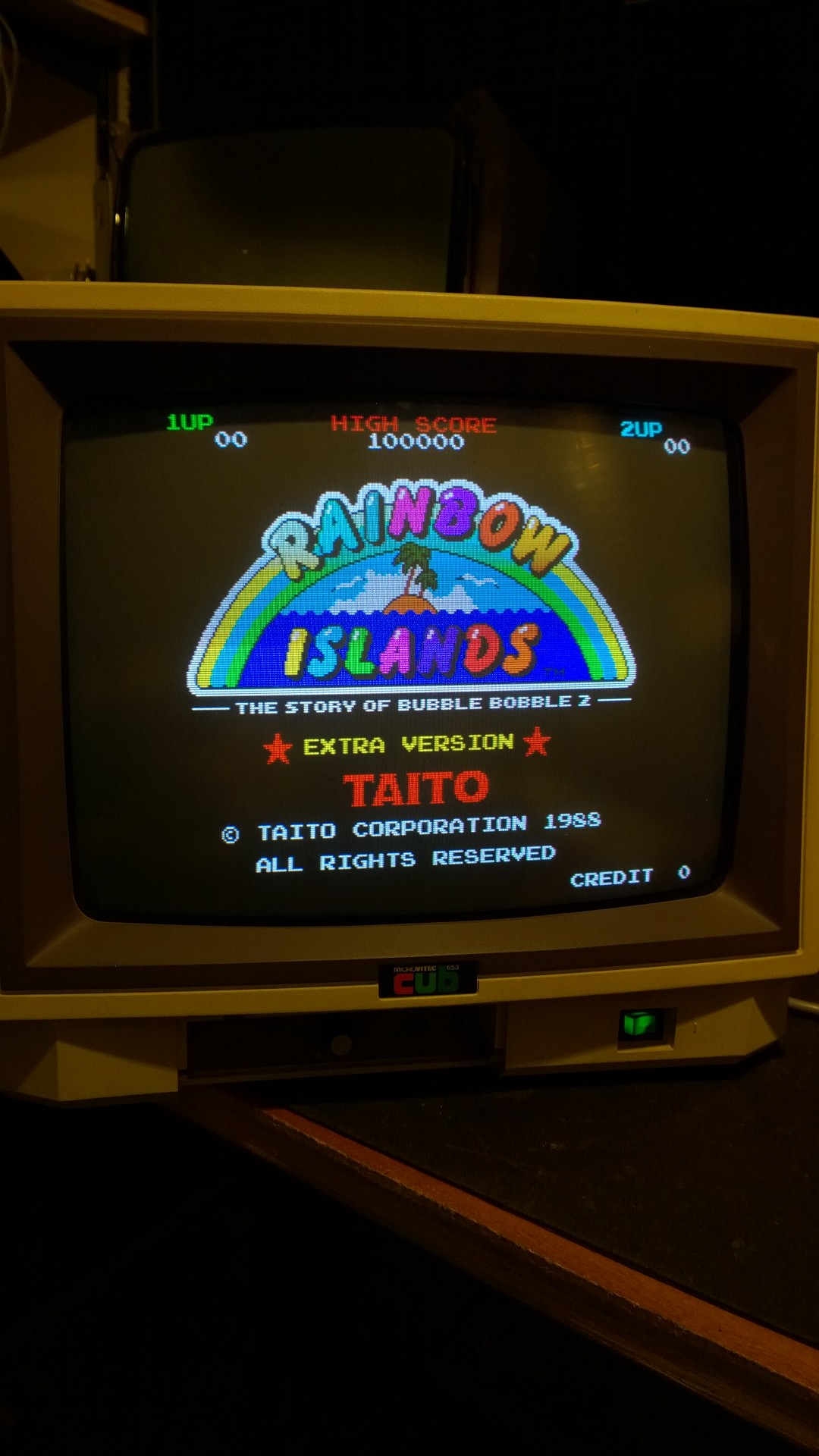

Picked up a nice Cub monitor at the weekend, a 1452 I believe but I may have that wrong from memory.
I got it to use with my Fluke but it should essentially be the same as arcade as my Fluke was previously running on a Polo 14" with no special trickery that I can remember.
So I've initially tried it on my Jamma rig and I can't get a picture that is anything other than very white and blown out. I think it worked reasonably for a few seconds before it went like it so pretty sure it's a fault rather than a bad setup.
What I've tried:
Where do I go from here? Any ideas?
Before anyone says "cap kit", I don't believe in them, but I'm happy if anyone can recommended any particular caps that could impact the black level. To be honest, I'm struggling to spot any on the schematics.
I got it to use with my Fluke but it should essentially be the same as arcade as my Fluke was previously running on a Polo 14" with no special trickery that I can remember.
So I've initially tried it on my Jamma rig and I can't get a picture that is anything other than very white and blown out. I think it worked reasonably for a few seconds before it went like it so pretty sure it's a fault rather than a bad setup.
What I've tried:
- Ensured that the TTL / Analog jumpers are set to Analog. In this mode, the contrast control on the front has no effect.
- Start by turn all R/G/B black level controls fully off. This gives a good colour but it's heavily if not totally blue screen. Tells me the guns are good though!
- Performed a black level setup procedure on the monitor, so with HV (VR4), brightness and A1 (grid) all at minimum I have set the BL for R/G/B to 140V each as per the manual. By now we are back up to very white.
- Removed and verified that both the brightness pot and the contrast pots are good and any connectors are making good connections (contrast is a remote control).
Where do I go from here? Any ideas?
Before anyone says "cap kit", I don't believe in them, but I'm happy if anyone can recommended any particular caps that could impact the black level. To be honest, I'm struggling to spot any on the schematics.