- Credits
- 763CR
Post edited to summarise faults and fixes (original 1st post shown below)
Fault #1
Symptom: no V-SYNC
Check: 32H 4H (outputs on pin 14 of E5 and 13 of D5, inputs on A6 pins 11 and 12) - both ok
Check: Outputs of counter @A4 - outputs stuck low.
Resolution: Replace LS191 @A4 - V-sync working
Fault #2
Symptom: no sound (self test)
Check: Pokey pin 37 - ok
Check: LM324 pin 5 @ N10 - stuck high
Check: Continuity between Pokey pin 37 and LM324 pin 5 - no connection
Resolution: Reflow pin 37 on pokey sockect (dry joint) - audio output working
Fault #3
Symptom: RAM Fault. Self test indicates ram @ M4 is faulty.
Action: Replace RAM IC (socket)
Symptom: RAM Fault. Self test still indicates ram @ M4 is faulty.
Action: Swap RAM from location that tests as good to M4
Symptom: RAM Fault. Self test still indicates ram @ M4 is faulty.
Check: Use Fluke to test RAM - RAM DCD ERR @ 0009 BIT 4
Check: Inspect PCB - damaged track between M4 and N4 corresponding to DEAD4 (RAM Address line)
Resolution: Flow solder over break in track - RAM now verifies as good with fluke AND self test.
Fault #4
Symptom: Static blue screen
Check: Pin 40 (_RESET) on CPU - stuck low
Check: 74-93 @ D4 output - no activity
Resolution: Replace 74-93 @ D4 - blue screen now "bounces" as watchdog is "barking"
Fault #5:
Symptom: Jumping blue screen, no self test etc.
Check: MADSEL - no activity
Check: 74ls74 flip flop @ F7 - no ouputs
Resolution: Replace 74ls74 @ F7 - game "works" but with screen corruption
Fault #6:
Symptom: Game "works" but with screen corruption
Check: Full diagnostic with fluke (BUS/ROM/RAM) - all verify fine, ROM checksums tally.
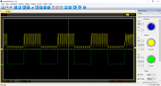
Check: Go back to the start and check the sync circuit outputs with a scope instead of a logic probe - "corrupt" output on pin 3 of LS191@A4
Check: Verify downstream ICs function as expected - apparent short between pins 5 and 6 of LS153@K3
Resolution: Replace LS153@K3
Result: Game runs!
---------------------------- Original First Post ----------------------------
I'm working on a couple of MC PCBs at the moment, so I'll write them up here as I go. (So I don't forget!)
In general the MC self test is pretty good.... but quite often boards have faults that prevent them getting that far.
So the first PCB I'm working on won't self test. At this point I always start with the SYNC circuits (confusingly nothing to do with SYNC line on pin 7 of the CPU)
The SYNC circuits are responsible for all the timing signals on the board, anything wrong here and you won't get far.
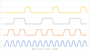
So... I have a good 10MHz, 5MHz and H signals including H-Sync.
BUT I have no V-SYNC.
V-SYNC is based on the 32H and 4H (and _FLIP, but that's not a consideration right now)
Both of those (outputs on pin 14 of E5 and 13 of D5, inputs on A6 pins 11 and 12) are fine.
Following the circuit through checking with a logic probe I can see that a couple of outputs on counter at A4 are stuck low.
Replacing the counter at A4 means I now have V-SYNC and all the "V" signals seem ok (1V .... 128V)
Still no sound on self test.
I check that my test rig is working right - yep the "TEST" is low on the MC PCB.
Checking pin 37 on the Pokey shows the pattern I'd expect for self-test audio (it pulses in the sequence of the self-test "beeps"!), so there's something wrong with the audio output as well. That's my next step for investigation, probably starting around the LM324 on the audio output.
yorkshire_spam2018-11-20 16:32:24
Fault #1
Symptom: no V-SYNC
Check: 32H 4H (outputs on pin 14 of E5 and 13 of D5, inputs on A6 pins 11 and 12) - both ok
Check: Outputs of counter @A4 - outputs stuck low.
Resolution: Replace LS191 @A4 - V-sync working
Fault #2
Symptom: no sound (self test)
Check: Pokey pin 37 - ok
Check: LM324 pin 5 @ N10 - stuck high
Check: Continuity between Pokey pin 37 and LM324 pin 5 - no connection
Resolution: Reflow pin 37 on pokey sockect (dry joint) - audio output working
Fault #3
Symptom: RAM Fault. Self test indicates ram @ M4 is faulty.
Action: Replace RAM IC (socket)
Symptom: RAM Fault. Self test still indicates ram @ M4 is faulty.
Action: Swap RAM from location that tests as good to M4
Symptom: RAM Fault. Self test still indicates ram @ M4 is faulty.
Check: Use Fluke to test RAM - RAM DCD ERR @ 0009 BIT 4
Check: Inspect PCB - damaged track between M4 and N4 corresponding to DEAD4 (RAM Address line)
Resolution: Flow solder over break in track - RAM now verifies as good with fluke AND self test.
Fault #4
Symptom: Static blue screen
Check: Pin 40 (_RESET) on CPU - stuck low
Check: 74-93 @ D4 output - no activity
Resolution: Replace 74-93 @ D4 - blue screen now "bounces" as watchdog is "barking"
Fault #5:
Symptom: Jumping blue screen, no self test etc.
Check: MADSEL - no activity
Check: 74ls74 flip flop @ F7 - no ouputs
Resolution: Replace 74ls74 @ F7 - game "works" but with screen corruption
Fault #6:
Symptom: Game "works" but with screen corruption
Check: Full diagnostic with fluke (BUS/ROM/RAM) - all verify fine, ROM checksums tally.
Check: Go back to the start and check the sync circuit outputs with a scope instead of a logic probe - "corrupt" output on pin 3 of LS191@A4
Check: Verify downstream ICs function as expected - apparent short between pins 5 and 6 of LS153@K3
Resolution: Replace LS153@K3
Result: Game runs!
---------------------------- Original First Post ----------------------------
I'm working on a couple of MC PCBs at the moment, so I'll write them up here as I go. (So I don't forget!)
In general the MC self test is pretty good.... but quite often boards have faults that prevent them getting that far.
So the first PCB I'm working on won't self test. At this point I always start with the SYNC circuits (confusingly nothing to do with SYNC line on pin 7 of the CPU)
The SYNC circuits are responsible for all the timing signals on the board, anything wrong here and you won't get far.
So... I have a good 10MHz, 5MHz and H signals including H-Sync.
BUT I have no V-SYNC.
V-SYNC is based on the 32H and 4H (and _FLIP, but that's not a consideration right now)
Both of those (outputs on pin 14 of E5 and 13 of D5, inputs on A6 pins 11 and 12) are fine.
Following the circuit through checking with a logic probe I can see that a couple of outputs on counter at A4 are stuck low.
Replacing the counter at A4 means I now have V-SYNC and all the "V" signals seem ok (1V .... 128V)
Still no sound on self test.
I check that my test rig is working right - yep the "TEST" is low on the MC PCB.
Checking pin 37 on the Pokey shows the pattern I'd expect for self-test audio (it pulses in the sequence of the self-test "beeps"!), so there's something wrong with the audio output as well. That's my next step for investigation, probably starting around the LM324 on the audio output.
yorkshire_spam2018-11-20 16:32:24
")
