Moon Cresta - MC-1FJ

minwah

Active member
Feedback
3 (100%)
Credits
238CR
A friend of mine has a Nichibutsu Moon Cresta cocktail with non-working PCB.

Initial state: yellow screen with some other coloured garbage, constant tone.

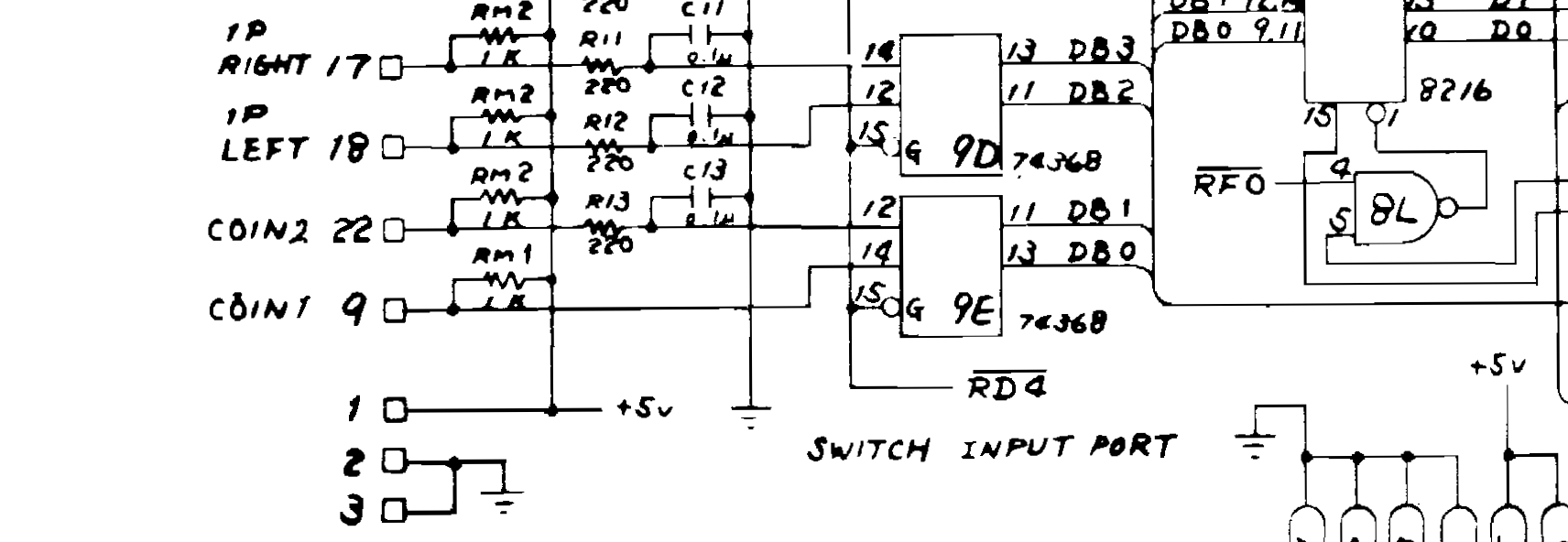
Checked pcb for bad joints, reseated chips, read socketed eproms MCS 1-8. MCS 7 bad - reprogrammed. (Used Mini Pro programmer, M2716 eproms, had to use Linux commandline software to set pulse speed to 45ms).

Result:

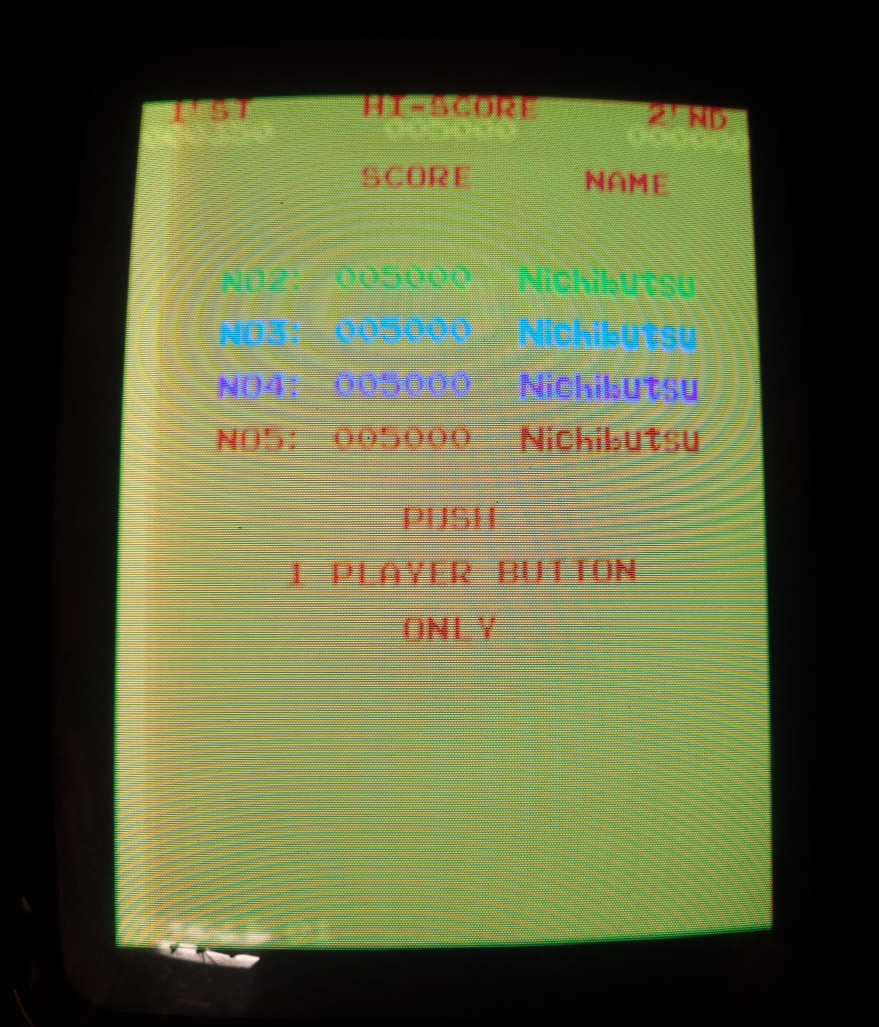
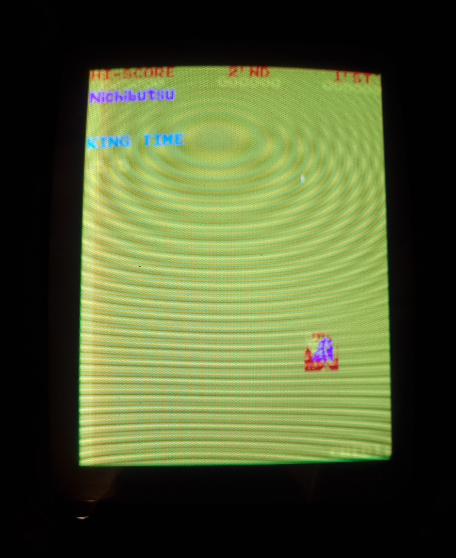
* Game now 'working', text characters ok, controls work, sound correct

* Colours incorrect

* Sprites corrupted

* Starfield not visible

* Odd things happening:

- screen sometimes 'scrolls' horizontally by 1 character at a time

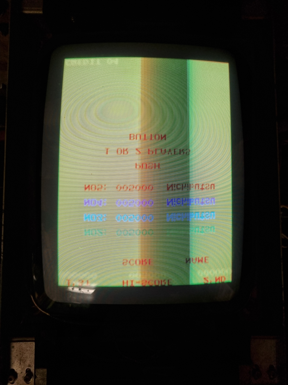
- screen sometimes flips during attract...characters displayed in same order as when not flipped

- only 1 enemy shown

- something part of the screen goes fuzzy, like sync is off

mc_colours.jpg


mc_sprites.jpg


mc_flipped.jpg


Next:

* Read colour prom

* Desolder & read graphics eproms MCS A-D
 

minwah

Active member
Feedback
3 (100%)
Credits
238CR
Minor update...

Read the colour prom which is fine. Went to desolder the graphics eproms and my desoldering gun has packed up (doesn't warm up) so guess I'll have to try to fix that...

Made an adaptor for my jamma test rig, now on the bench the sound isn't working, nor the coin input. Not had much time to look into that, but the coin input is reaching the 74LS368 at 9E (pin 14 goes low when coin switch closed...) so I'm sure the jamma adaptor is wired correctly. However I'm not sure what the output (pin 13) should be doing...it's always toggling low/high and doesn't change when the input is low. Do I need to use a scope to check that output?

Screenshot_2022-09-27_at_09.41.18.png


Also since they were socketed I swapped the two M5L2101AP 'control data store area' ram chips, and got different results on-screen (characters flashing colours, more sprites visible), so at least one of these chips is bad. (I swapped them back to verify the behaviour went back to how it was, so I'm sure it wasn't just the reseating that caused the change).

minwah2022-09-27 10:37:43
 

philmurr

Active member
vacBacker
Feedback
46 (100%)
Credits
2,302CR
The right hand side of the 368 is connected to the common data bus (DB0, DB1...etc) so if you look at it using a logic probe all the DBx lines will almost always be pulsing. The outputs are usually high impedance unless that chip is selected at which point its output are put onto the data bus.

You can check the output of the 368 in-circuit if you have something clever such as SLICE. Otherwise you will need to test the outputs out of circuit, a scope won't help.

For Moon Cresta one side of the speaker usually needs to be connected to 0V (unlike Galaxian) so that may be your issue with no sound
 

minwah

Active member
Feedback
3 (100%)
Credits
238CR
philmurr said:
The right hand side of the 368 is connected to the common data bus (DB0, DB1...etc) so if you look at it using a logic probe all the DBx lines will almost always be pulsing. The outputs are usually high impedance unless that chip is selected at which point its output are put onto the data bus.

You can check the output of the 368 in-circuit if you have something clever such as SLICE. Otherwise you will need to test the outputs out of circuit, a scope won't help.

I don't have anything clever so I'll have to remove it. I don't think I have any way to test it (thought my Mini Pro eprom programmer may do it, but doesn't seem to support the 368)...I guess I could swap it for one of the others to see if that makes a difference.

For Moon Cresta one side of the speaker usually needs to be connected to 0V (unlike Galaxian) so that may be your issue with no sound

I did do that (just connected the (-) speaker pin in my jamma adaptor to ground) but I'll go back and make sure I haven't made a mistake.

Many thanks for the help!
 

minwah

Active member
Feedback
3 (100%)
Credits
238CR
minwah said:
the coin input is reaching the 74LS368 at 9E (pin 14 goes low when coin switch closed...)

One other thing that seems odd...what I said above is true but when the switch is open the pin is neither high or low (no reading on logic probe). Shouldn't it be high? It looks like it to me from the schematic.

I tested all the other input pins on the 368s and they are all high until the relevant switch is closed.
 

minwah

Active member
Feedback
3 (100%)
Credits
238CR
Think I've answered the above myself. Measured the voltage at RM1 and it has <1V at the pin connected to the 368 for coin 1. Other pins on RM1 measure 5V as expected. So seems like RM1 is faulty.
 

minwah

Active member
Feedback
3 (100%)
Credits
238CR
minwah said:
Think I've answered the above myself. Measured the voltage at RM1 and it has <1V at the pin connected to the 368 for coin 1. Other pins on RM1 measure 5V as expected. So seems like RM1 is faulty.

I measured the resistance of each of the resistors of RM1 and pin 4 (connected to coin) was low, but pulled it out of circuit and it measures fine (1k ohm), so it's not that - put back in.

Next problem, now the board doesn't boot, just resets with garbage on screen. Re-checked the roms & reseated all socketed chips & no difference (except some slight difference in garbage after reseating roms...perhaps an iffy socket). Maybe the bad ram I found before is to blame...still waiting for replacement to arrive.

Anyway thought I'd crack on desoldering the gfx roms as I know at least one is bad. However my desoldering gun (or rather I) is making a right mess of it, removing the pads while not removing all the solder. Anyone got anyt tips how to deal with that? Going to have to remove the solder from the top, I guess wick is the only way?
 

minwah

Active member
Feedback
3 (100%)
Credits
238CR
It's been a while but had another look at this last night...

I've programmed new graphics roms A-D which I thought would sort the colours & corrupt sprites...however it made no difference whatsoever. (Some of the old roms had to be cut out so I could not read them all to verify).

Then I replaced the bad RAM (M5L2101AP), and this has fixed the corrupt sprites and all other weird issues with the video (excluding wrong colours).

So now the outstanding issues are:

* Bad colours
* Inputs don't work
* No sound

I'm going to take the board back round my friends to try in the cabinet to check if the inputs/sound work there (in case I've made a mistake with my loom).

Does anyone have any suggestions what to check next for the bad colours, bearing in mind I've checked the colour prom and gfx roms?
 

Lurch666

Active member
Feedback
21 (100%)
Credits
4,142CR
For bad colours look at the chips that generate bullet,missile and stars.
If these are on all the time the screen is filled with a single colour for a bullet or star.
 

jonhughes

Active member
vacBacker
Feedback
51 (100%)
Credits
1,112CR
Have you got a copy of the Galaxian repair trouble shooting guides? The hardware is similar and it gives information on what functions certain chips perform. Have used the guide to cross troubleshoot Moon Cresta hardware before. On Galaxian hardware I think three chips can have an affect on colour. The PROM is one and another is a 74ls273. Can’t remember what the other is.

It should also give you some clues on sound, but my sound probe. I always found, is the best for tracking sound faults.
 

minwah

Active member
Feedback
3 (100%)
Credits
238CR
Have you got a copy of the Galaxian repair trouble shooting guides? The hardware is similar and it gives information on what functions certain chips perform. Have used the guide to cross troubleshoot Moon Cresta hardware before. On Galaxian hardware I think three chips can have an affect on colour. The PROM is one and another is a 74ls273. Can’t remember what the other is.

It should also give you some clues on sound, but my sound probe. I always found, is the best for tracking sound faults.

I do have the Galaxian troubleshooting guide...thanks for the tip. Also I had a quick look at the Moon Cresta schematic and it labels the chips responsible for stars so I guess that is a good place to start. (I've checked the PROM already).

I think I'll leave sound til last but what is your sound probe?
 

NivagSwerdna

Active member
Feedback
1 (100%)
Credits
744CR
There are bad colours... and then there are bad colours.... it depends on which graphic element you are discussing. If the sprite RAM is socketed... try swapping them around.

FYI I'm referring to the 27LS00s at 1N, 1P, 1R, 1S and 1T

(Maybe that should really be called a line buffer rather than Sprite RAM?)
 
Last edited:

minwah

Active member
Feedback
3 (100%)
Credits
238CR
There are bad colours... and then there are bad colours.... it depends on which graphic element you are discussing. If the sprite RAM is socketed... try swapping them around.

FYI I'm referring to the 27LS00s at 1N, 1P, 1R, 1S and 1T

(Maybe that should really be called a line buffer rather than Sprite RAM?)
I'm sure I tried swapping those RAM chips last year and it didn't make any difference...I'll double check that.

The main problem with colours is that the background is yellow (not black) - exactly as in the screenshots at the start of this thread. The corrupted sprites & text issues are now fixed but the colours are the same.
 

Philson

Newbie
Credits
18CR
Happy New Year,
can anyone direct me to somewhere that I can download the Moon Cresta ROMs please?
I have 12 in total over the three PCBs, labelled MR1 to MR12
i think I may have a issue with MR1, as when I remove it the screen displays random characters with stars moving in the background, when I plug it back in I can see BAD RAM 2
I have check the RAMs with a little device I bought off eBay, and all seem to be ok.
many thanks
 
Top