Resistor network replacements

RGP

Meeter & Greeter
Feedback
5 (100%)
Credits
2,039CR
Run up against a brick wall I don't know how to get past. Have a couple of boards that have minor fails because of those resistor network / resistor/cap network packages just after the input of the controls.

karate champ - player 1 stuck in down position due to this part.

TMNT2 - can't coin up P1 or P2 due to bad RN part.

Is there a way to work around these or are there any equivalents out there that can be purchased.

The one on the TMNT2 board is part 005273

I can't remember the one on Karate Champ.

I can't picture the schematic in my head of the TMNT2 one as there's VCC and GND involved in the part and it seems to act as a pull-up resistor unless there's a cap in there as well for debounce which then the GND would make sense.

+5 ---- P/UP --- SPUR TO RECEIVING IC --- CAP --- GND

RGP2016-03-29 19:45:16
 

abaxas

Active member
Credits
124CR
DIPS? SILS? Weird stuff?

If you know what it is, you can just 'bodge' with something homebrew. Even make a little PCB for it if you have the equipment.

How hard can some resistors and caps be.
 

RGP

Meeter & Greeter
Feedback
5 (100%)
Credits
2,039CR
Cheers guys, agree this shouldn't be difficult, just never had to do one before.

Think its more figuring out what was in the original package than anything and how it was wired up.
 

grobda

"Look at the size of that thing!"
vacBacker
Feedback
7 (100%)
Credits
1,061CR
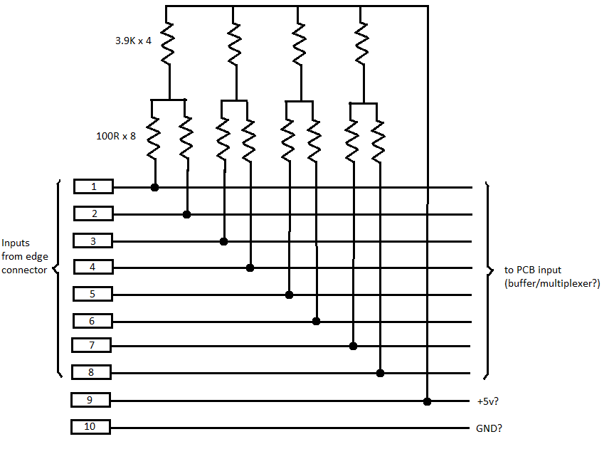
Looks like pairs of 100R tied to 3.9Ks then all tied to GND

so arent they just pullups? wonder why bother with the 100R? - the 5% variance of the 3.9's is 195R

I assume the cap would be a filter between pin 9 and 10.

Have you measured the resistance between 1-8 and 9? I had a bad custom sil and turned out there was a hairline crack in it I didn't notice at first.

edit: corrected pin numbers.

grobda2016-03-30 09:38:03
 

RGP

Meeter & Greeter
Feedback
5 (100%)
Credits
2,039CR
So a 4.7k would do it as a replacement.

8/9 decoupling cap possibly? .1nf?

Where i'm getting stuck is the output pin - i'm used to seeing pull ups across a line meaning the line goes from input pin to chip and a pull up is paralleled onto the line to attenuate the signal up.

So i think what you were saying is that the initial pullup then has a 100R to take the signal to the output pin as they're not directly connected on the board.

Fascinating!

I have so much still to learn.

Am i on the right track here?RGP2016-03-30 08:06:16
 

grobda

"Look at the size of that thing!"
vacBacker
Feedback
7 (100%)
Credits
1,061CR
I'm guessing its wired like this;

inputs.png


I.E. a slightly odd way of giving each input a pullup, I have no idea why he did it that way. But then I'm relying on a 25 year old Electronics GCSE and a bit of informal tinkering. If I were replacing it i'd probably put a 4.7k on each input line and tie them all to +5v, a normal resistor array could do the trick, with the option of a 104Z cap between 9 and 10.
 
Top