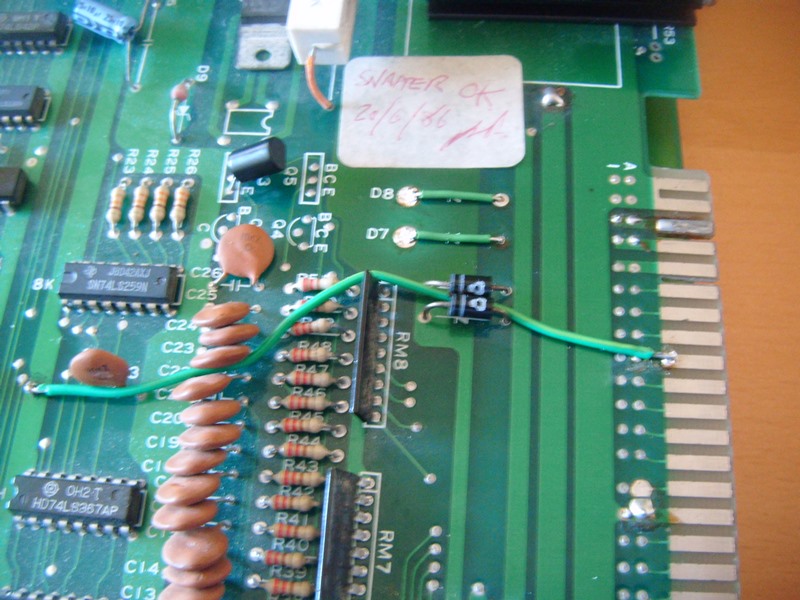
I took a trip over to Nads (Equites) last weekend and he said he had a project for me. I was reluctant at first and wondered what on earth it could be (I should have been a little more thankful) because I have quite a few things on already (Need to get looking at that Moon Cresta again).
Anyway he handed me a Snapper / Hangleyman PCB which is a Clone of Pacman only cut in half and linked by a ribbon cable to make it two layer.
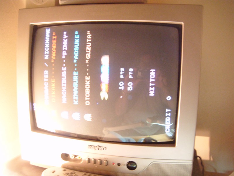
I got in from work early today and had a spare hour so I thought I'd fire it up and was presented with this:
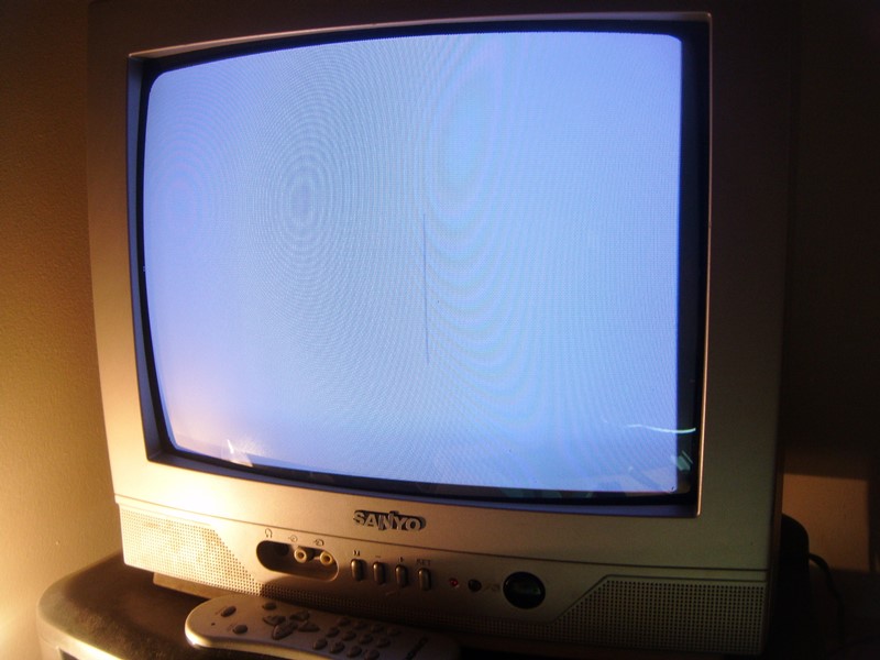
It's a white screen with some black thin lines at the half way. I instantly recognised the lines as Pacman being chased across the screen in demo mode. Changed the bi-polar at 4A and I get decent graphics, however, all the characters had jailbars on them (sorry no photo). Rewind a year or so and I put a similar fault in the Tech section - identical fault, which I managed to fix but couldn't remember.
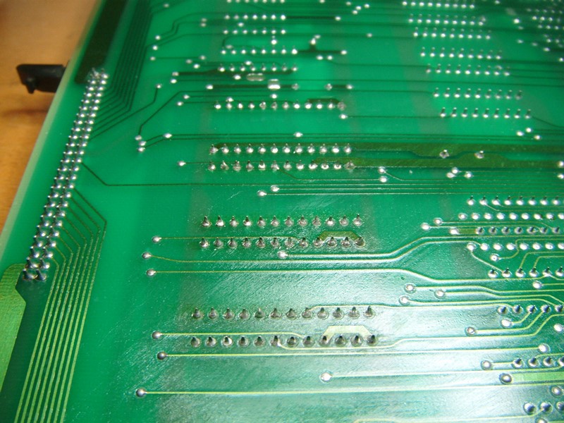
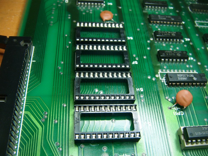
Went out for a game of squash and remembered during the game it was a dodgy socket on one of the EPROMs.
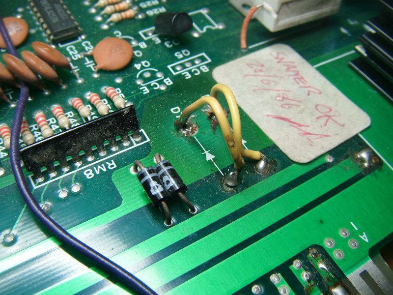
Got back in and decided to fix the sound before replacing any sockets - the amp was missing and I wanted to make sure this would work before thinking about the sockets:
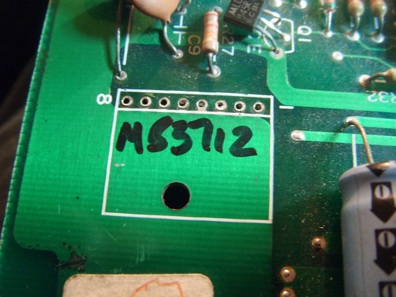
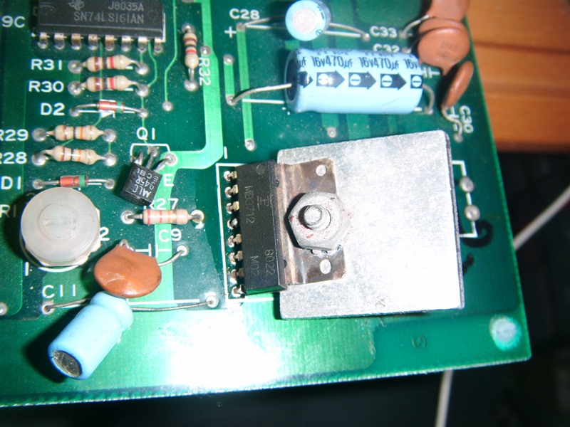
It's an MB3712, poached one from a donor board and now I have static noise:
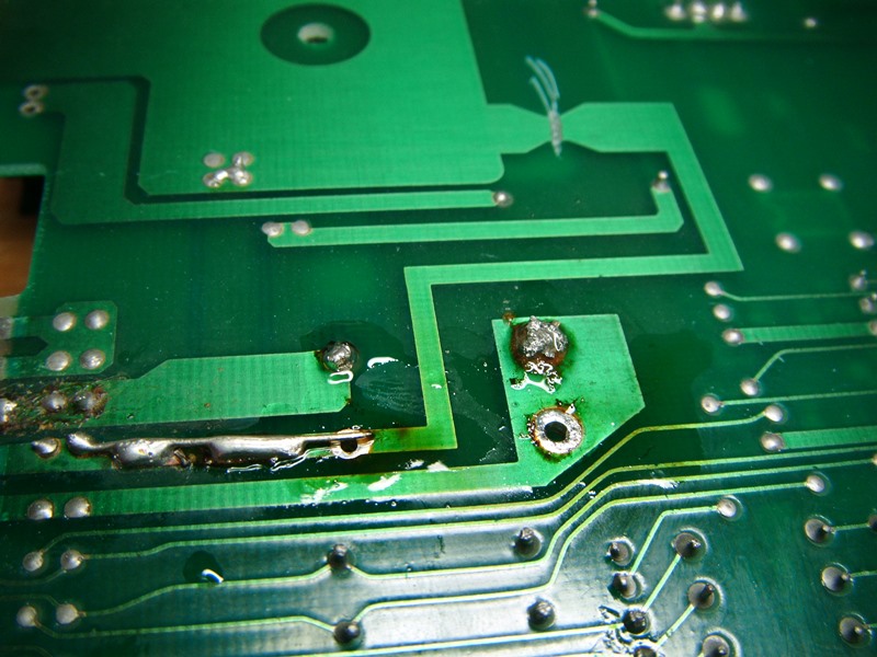
A while ago I was indeed very lucky to buy some Pacman bits from a seller. In the purchase there were a ton of chips including ROMs and bipolars all neatly labelled.
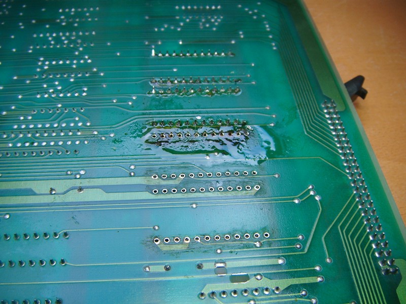
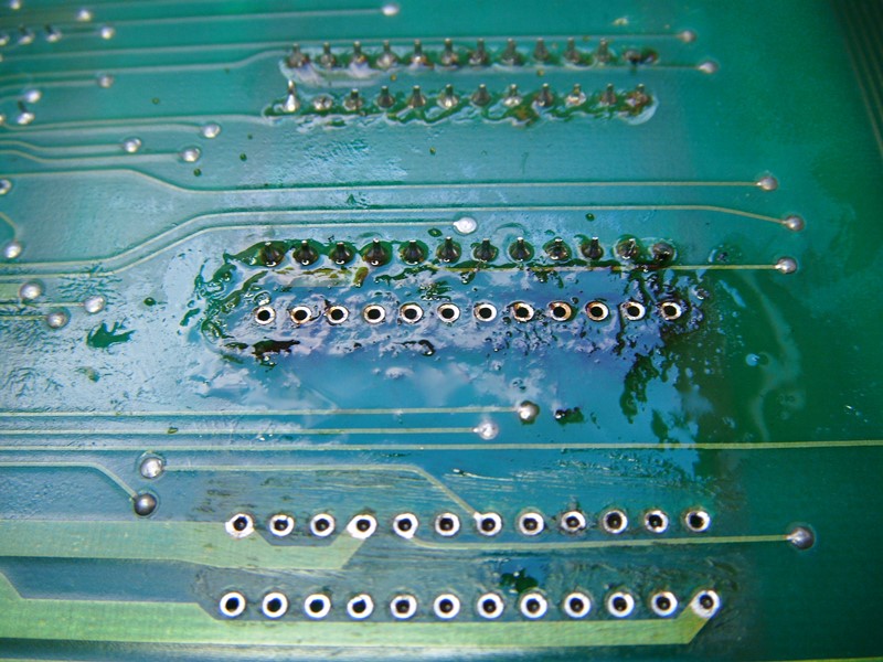
Found the legs on the chips at 1M and 3M had practically disintegrated, so popped the spares in and now I have fully working sound.
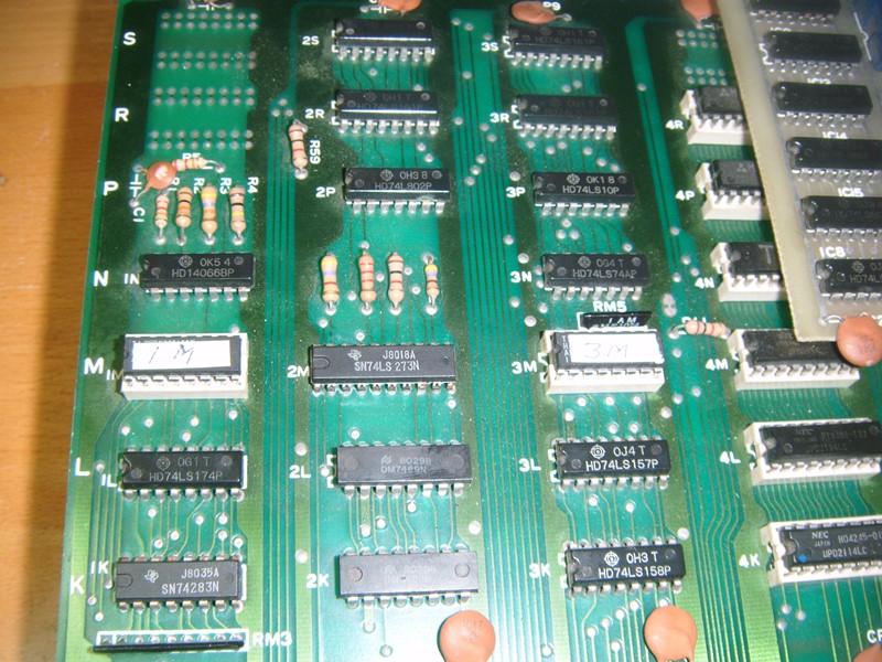
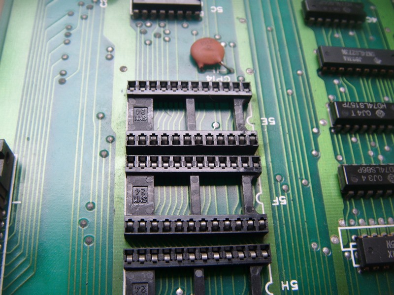
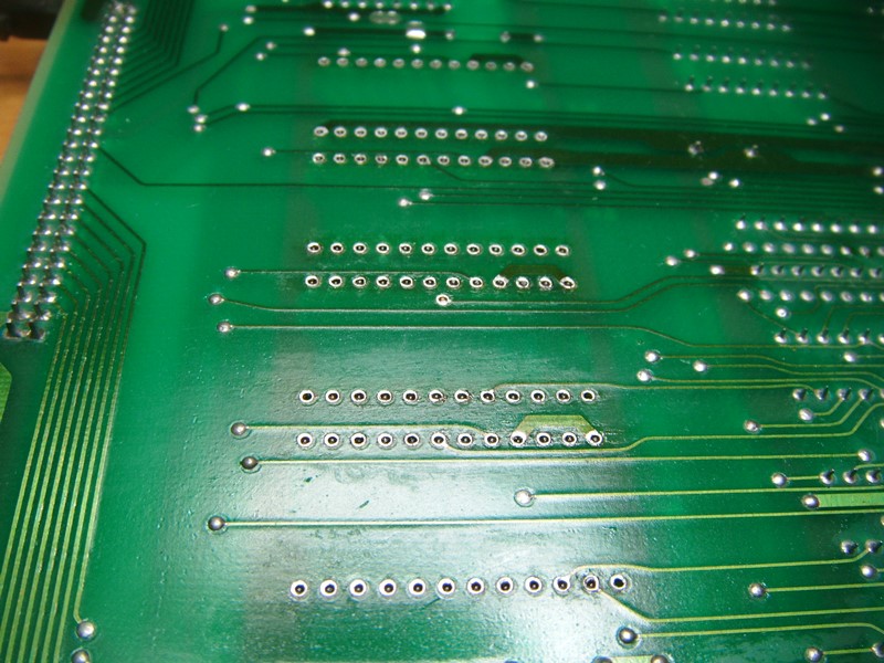
Having remembered the socket problem I decided to push the legs inwards on the chips to scratch a contact on the sockets. It's worked but they will need replacing and the game is now functioning.

Anyway he handed me a Snapper / Hangleyman PCB which is a Clone of Pacman only cut in half and linked by a ribbon cable to make it two layer.
I got in from work early today and had a spare hour so I thought I'd fire it up and was presented with this:
It's a white screen with some black thin lines at the half way. I instantly recognised the lines as Pacman being chased across the screen in demo mode. Changed the bi-polar at 4A and I get decent graphics, however, all the characters had jailbars on them (sorry no photo). Rewind a year or so and I put a similar fault in the Tech section - identical fault, which I managed to fix but couldn't remember.
Went out for a game of squash and remembered during the game it was a dodgy socket on one of the EPROMs.
Got back in and decided to fix the sound before replacing any sockets - the amp was missing and I wanted to make sure this would work before thinking about the sockets:
It's an MB3712, poached one from a donor board and now I have static noise:
A while ago I was indeed very lucky to buy some Pacman bits from a seller. In the purchase there were a ton of chips including ROMs and bipolars all neatly labelled.
Found the legs on the chips at 1M and 3M had practically disintegrated, so popped the spares in and now I have fully working sound.
Having remembered the socket problem I decided to push the legs inwards on the chips to scratch a contact on the sockets. It's worked but they will need replacing and the game is now functioning.