Space Invaders PCB advice needed

RGP

Meeter & Greeter
Feedback
5 (100%)
Credits
2,039CR
Hey Guys

I have hit a total brick wall and need a little help.

I have a non-booting Space Invaders pt 2 3 layer cocktail stack black & white version.

Comes up to static garbage on screen. CPU is known good and sticking my braze kit in gets no furher so i've dragged out he fluke 9010 amd an 8080 pod. Both ROM amd sound boards are known to be 100% working also.

I have no bus conflicts so CPU to buffers/drivers are ok.

Attempt to ROM test $2000-3FFF returns "stuck BTS 40 @ 2000". Theres another ram region higher up at 4000-5fff and testing anywhere in that region produces the same results.

WRITE $2000 with 00 reads as 00
WRITE $2000 with FF reads as BF

So this confirms that D6 is geting stuck LO somewhere.

Typically this would be a 244 or 245 but these boards use 241's to trancieve the databus.

My problem starts with the schematics - they're really badly printed around the CPU so i've had to manually trace a lot of the board.

D6 is pin 5 on the 8080, this goes to pins 15 and 16 on the 241 at IC28. The 241 is wired in a loop configuration due to the RAM. One of those pins is an input, the oher is an ouput whuch would return to the main databus dependent on the 1G/2G selection state - so am i right in thinking they used these instead of a 245 because 245's hadn't been invented at that point?

Pin 4 of IC28 heads off north to the resistors near the RAM and to a 174 at IC44.

Signal arrives at pin 6 of the ram as expected, using a loop write amd stopping it amd restarting it I see all the data in pins at the ram change state correctly.

I'm fairly convinced the RAMs are ok because reading ROM produces byte values that are also incorrect so my theory is in the return chain from the RAM or ROM to the CPU.

PIn 7 is data out on the ram chips.

This seems to go to a 7404 at the right hand side of the board, my comparator reckoned this chip was bad but out of circuited tests fine.

The 04 seems to go to a chain of 174 and then 153's before ending up back at the 241 at IC28 which outputs to pin 15 which goes back to D6.

The 241 has been out of circuit and tests fine too and i have new spares and no change there so its not a circuit loading issue.

Anyone had similar problems?

Given i can see data reach the RAM and the ROM reads incorrectly, is my theory correct in terms of return path to the CPU?

Any other advice on tackling this?
RGP2017-01-11 02:31:10
 

philmurr

Active member
vacBacker
Feedback
48 (100%)
Credits
2,374CR
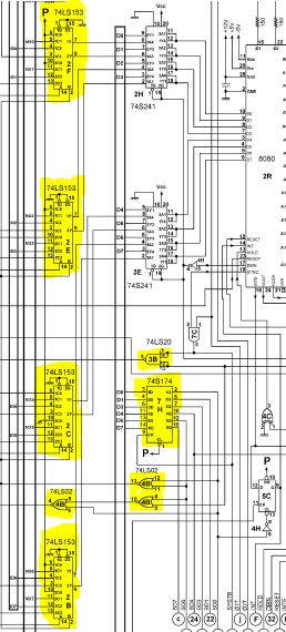
Have you checked 7H (74174), 7C & 4B, & the 153's at 2C, 2E, 2F?

The 8080 is a bit odd in that it places "status" information on the data bus and the above IC's decode the status to do the various enables.

The 153's mux the various data onto the data bus (and are renowned for failing, at least on Williams boards). The 174 and associated logic mentioned above generate the control signals for the 153's.

Have a look at Dave Langley's site for a clear (redrawn) version of the schematics. Chip positions may be different but the circuits are essentially the same around the CPU.
 

andrewsm

Active member
Feedback
1 (100%)
Credits
485CR
Later on when I get in I will take a look for you as debugged my boards so have a good idea how they work. Make sure the reset line is tied to ground as the PSU usually resets boards plus silly question but needs -5V and +12V.
 

RGP

Meeter & Greeter
Feedback
5 (100%)
Credits
2,039CR
Cheers guys

I forgot to put in the original post this is a Taito board set, the references Phil gave don't match up. I'm using the schematics from Dave Langley's site but they're quite smudged around the CPU section.

Also unless i've missed something some of the IC numbers don't match.

The board has IC numbers next to each chip in the silkscreen.

I can verify the loom is good as i've a working set I just fixed a graphics problem on so i've played swap the boards so i know its just the CPU board on this set.

This all started with the other set having an audio issue. I got the amp going again but then found it had a missing saucer hit sound. The braze kit has tests so you don't need to play the game but the CPU wasn't socketed and i didn't want to unnecessarily take the CPU out. So knowing i had to fix this other one anyway i thought i'd get that going.

To anyone who thinks PCB repair is easy peasy - just wait till your time gets sucked dry like this.
 

philmurr

Active member
vacBacker
Feedback
48 (100%)
Credits
2,374CR
I've had a look at the other schematics and the numbers on the schematic don't even tie up with the numbers on the PCB overlay
smiley5.gif


So if you're still working your way through this, I think the highlighted chips below are the ones to look at (just ignore the IC references)

SI_capture.JPG
 

RGP

Meeter & Greeter
Feedback
5 (100%)
Credits
2,039CR
Phil, that's an amazing diagram, which version is that? The one i've been looking at is really blurry.

Also very confusing when you look at the sound section as there's a version of the board using an LM377 and one using an MB amp - the LM377 schematic part is buried in the middle so you scratch your head a bit.

Just looking at those references, I could imagine the integer being the vertical of the board from the bottom but the 2H, 3E don't match up right, they'd be at 3E, 4E realistically.

If that's a redraw of the 3-layer, i'd love to see the rest of it.

When you look at this in today's eyes and mindset, it was marvellous that it worked originally, the 8080's a simple CPU but the implementation looks like requirement and chips dictated design.

As a total side project, i'd be really interested in looking at re-implementing this game - not necessarily in FPGA but I bet the number of chips could be seriously reduced.

Sound section is a bit of a beast though.

Single board super reliable Space Invaders anyone?
smiley4.gif
 

RGP

Meeter & Greeter
Feedback
5 (100%)
Credits
2,039CR
Ok, update time.

First, thanks to philmurr, i've got a large format printed version and I traced out a lot of the chips from that schematic from the cocktail set so I know where a lot of the chips are now. i'll upload a list in a couple of days.

After going literally all around the houses on this and taking chips out of the board to test and put back, i've finally found the issue.....

...... it was the ram that done it guv'nor!

I had looked at pin 7 of the culprit (IC15) and seen changing signals coming out when reading back so i'd discounted it.

Anyway, I decided to look at the other pin 7's on the other RAMs and found the signal differed so I went across all of them and found that IC15 had the only different pin 7.

Removed from board, fitted socket and moved the one from another socket in to it and could read/write the location properly.

What I found out from this is that SI stripes its RAM locations across the two banks - the ones at the top are the EVEN numbered addresses - $2000, $2002 etc and the ones on the bottom near the CPU are the odd numbered addresses - $2001, $2003 etc.

Borrowed a 2107 off another board and the game boots.

Now I can return to my issue - missing sounds.

Somewhere that I can't find, is a repair log of fixing SI sound. I found that the braze kit doesn't work on the Taito cocktail boards for some reason - it depends massively on what Scott did to make these kits but in theory it should work as the code etc is the same but that's another story.

I'm looking for a way to take the sound board out of mute and trigger the saucer hit sound repeatedly - the braze kit would let you do this from the test menu.

Are there any other aftermarket/fan-made test roms for this board?

Anyone know a good way to trigger the sounds manually?

RGP2017-01-17 22:26:22
 

RGP

Meeter & Greeter
Feedback
5 (100%)
Credits
2,039CR
Thanks dude :)

That bottom link is extremely helpful, i'll give that a go for sure, like you say, it should work on both Midway and Taito boards. Had a look at the source, seems pretty straightforward and from my understanding of the licensing, Taito wouldn't let Midway change anything about the hardware or software side.
 

RGP

Meeter & Greeter
Feedback
5 (100%)
Credits
2,039CR
Update....

I seem to have had a deluge of Space Invaders cocktail table boards come through for repair since writing this thread initially.

This week in-between other boards, I had two come in, both colour cocktail versions, both non starts, both meaning squinting at my least favourite bit of the schematics - the CPU area.

Given I can use the Midway schemes as a mild reference to how the circuit works, it still meant a lot of headache finding out which chip is which - and the Midway's aren't pin to pin either I discovered.

Anyways, I started mapping out the CPU board in those sets. Figured it might be useful to other people.


I had one where the Fluke wouldn't RAM test past $201E - well this had to be something messing up the address lines - bus test passed just fine which I expected but turned out RAM-A4 was constantly LOW.

With this new drawing it took 5 mins to find the problem.

I'm going to finish this off over time - its drawn in Eagle as its the only thing I could put my hands on for OSX quickly.

There are some items i've added this evening without a board in front of me - the RAM chips - I had to make a custom library item for the TMS4060's.

Don't think its too bad for a first attempt _ever_ at using a schematic software.
 

Kaizen088

User
Credits
130CR
Nice work on tracing the schematic.

I feel your pain when working on SI PCB's, I've repaired three Taito 3-Layer PCb's in the last few weeks and swapping back and forth between the clean schematics and the crappy ones and trying to remember the correct chip number when there are two revisions of the Taito PCB set and the Midway chip numbers add to the confusion. Here's all my schematics.

I'm trying to chase down all available versions of Space Invaders Schematics.

I can't find anything for the US Taito 2-Layer Cocktail PCB.

Below is what I have already.

The US Trimline stuff was scanned in by myself.

I'm looking for any schematic not shown below or info sheets on troubleshooting, modifications, hacks, clones etc.

Taito Pt1 and Pt2 Colour 3-Layer PCB


Taito US Trimline Upright B+W


Taito L-Shaped Schematic


Midway L-Shaped


Intruder (Clone)


Converting from 2708 to 2716/2732


RAM Fault Troubleshooting


Kaizen0882017-03-15 14:07:34
 
Top