Yes, I did mean 'hoard', rather than 'board.

A long time ago in a ... oh, that joke's already been done once or twice.
Time for some Star Wars PCB repairs. Faced with fixing a minor fault on my working cab, I thought it was about time I dragged my other sets out of the attic and had a go at repairing them. In all there are 3 boardsets to fix.
Set 1
Symptoms: Intermittent sound problems. A mix of effects missed or incorrect sounds triggered.
Self-test sometimes showed a PIA RAM fault. Swapping the PIA with a known good part seemed to fix the problem for a while, then it came back. Suspected a dodgy socket and this was comfirmed by being able to vary the fault by pushing down on the chip.
Socket replaced. Fault gone.
Set 2
Symptoms: AVG output showing little more than a diagonal line. Sound is just noise.
AVG debug
Initially I worked on the AVG by swapping it into set 1. The output was just the same. Test mode beeps indicated no RAM/ROM faults, narrowing down the possible causes.
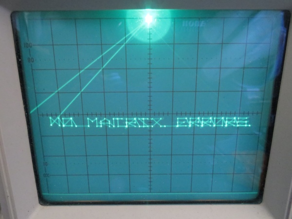
Star Wars isn't much fun when it looks like this:
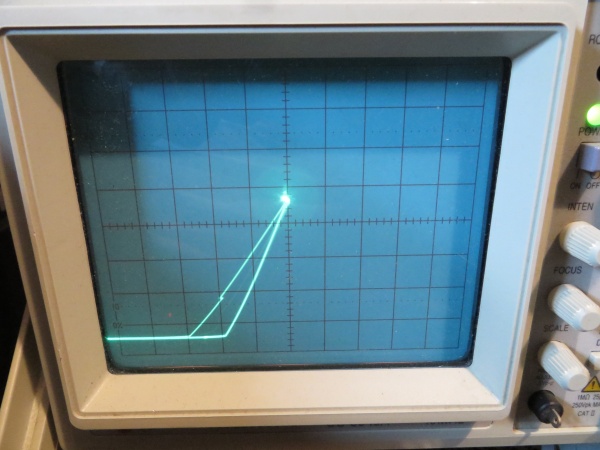
Neither X nor Y output ever went positive and there seemed to only be 3 different levels on each.
DAC inputs were certainly not stuck and the digital values were not representative of what were more-or-less just square waves on the X/Y outputs. The DAC outputs are virtual earths, so you can't probe them directly to verify; however, the analogue output circuitry can be checked for consistency, i.e. does the same crap appear at each stage? Yes it did, which at least suggested the last 2 amplifier stages were okay. Invert X and Y were grounded to check the analogue switches used for display flip. There was a chance something funky was happening with the first stage amplifier and/or centering switch for each axis. As each shared a chip with a known-working stage, I figured this was unlikely.
As a final check the BIP waveforms were compared. Again, due to the virtual earths, you can't check the final output, just the stages leading to it. No differences between the good and bad boards.
It was time to pull those DACs! The AM6012 DACs can be replaced with DAC312s which are still available from Farnell and the other usual suspects.
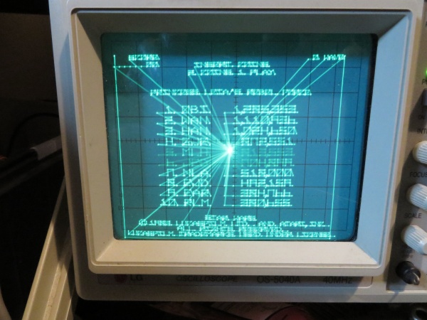
Swapping out the X-axis DAC produced some encouraging results (grid test running):
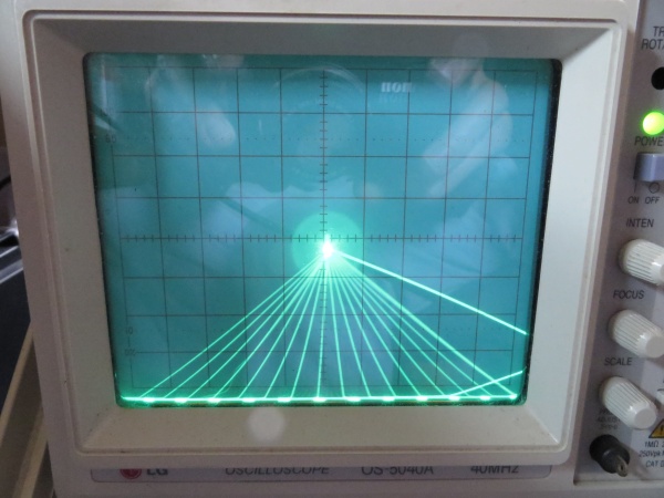
Looks vaguely grid-like. After swapping the Y-axis, I had sane vectors.. yay!
Everything looked good in-game, so I reintroduced the original CPU board.
CPU board debug
Alas, all was not well. There were no stars and the DIP switches were stuck in the 'off' state.
Starting with the easy stuff, I checked the DIPs. The switches themselves were all faulty and showed a very high 'on' resistance. Kind of surprising they all went together, but I'll take an easy fix any day of the week. New switches added and problems solved.
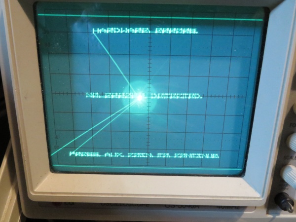
The missing stars proved somewhat more difficult. Test mode reported a mathbox failure, code B0000. The majority of the mathbox tests are really well documented in the operator's manual except for, you guessed it, test B. The manual says the test uses the block index counter and indirect addressing.
A quick poke around in the ROMs gave a better idea what was going on:
- Set block index counter (BIC) to 4
- Increment BIC 4 times
- Put a signature value into the mathbox RAM at word address 0x20. Apart from values for the B and C registers in the mathbox, the rest of the RAM is zeroed.
- Use indirect mode to read from word address BIC*4 and copy it to address zero.
- Check that the correct signature appears at the bottom of the RAM.
- Repeat from step 2, doubling the increment value and word address each time, i.e. a "walking one" on the address.
On failure, the value read from memory is reported. This would have been useful information IF the test had bothered to fill the RAM with a predictable pattern. As it was, the odds of zero being reported for a failure was pretty high.
Checking the values at the BIC registers (counters @ 3D, 3E and 3F) showed 0x108 on failure. Not a nice, power of 2. How did that happen?
Each counter was monitored individually using a logic analyser and appeared to function correctly. What's more, the final value was 0x100, which would be correct (the BIC is 9-bit, so 0x100 is the last value for a walking one test). Cursing the lack of trigger counters on my analyser I backed off the sample rate and could indeed see a second event which messed up the counter. At this point, the penny dropped: the test was repeating and 0x108 was the value you'd end up with if the msb of the counter had not been reset.
Here's the BIC circuitry:
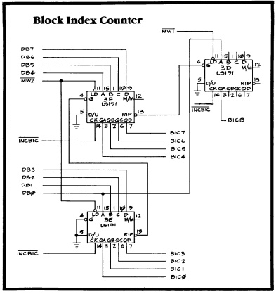
So, either MW1* wasn't being driven low to load the counter msb or the counter itself was faulty. A false 'high' wasn't being loaded, otherwise the test wouldn't have passed the first time around. I'd seen the carry into the msb working, so my money was on MW1* as it seemed unlikely the part would only fail to load and otherwise work properly. Wrong! Monitoring the counter activity showed MW1 going convincingly low and the output not changing.
Part 3D was swapped out and..
..even better, I flipped over to game mode and the sky was full of stars!

Next up is the soundboard for set 2, then it's the complete basket case that is set 3.
DaveSpicer2016-03-12 11:18:43
A long time ago in a ... oh, that joke's already been done once or twice.
Time for some Star Wars PCB repairs. Faced with fixing a minor fault on my working cab, I thought it was about time I dragged my other sets out of the attic and had a go at repairing them. In all there are 3 boardsets to fix.
Set 1
Symptoms: Intermittent sound problems. A mix of effects missed or incorrect sounds triggered.
Self-test sometimes showed a PIA RAM fault. Swapping the PIA with a known good part seemed to fix the problem for a while, then it came back. Suspected a dodgy socket and this was comfirmed by being able to vary the fault by pushing down on the chip.
Socket replaced. Fault gone.
Set 2
Symptoms: AVG output showing little more than a diagonal line. Sound is just noise.
AVG debug
Initially I worked on the AVG by swapping it into set 1. The output was just the same. Test mode beeps indicated no RAM/ROM faults, narrowing down the possible causes.
Star Wars isn't much fun when it looks like this:
Neither X nor Y output ever went positive and there seemed to only be 3 different levels on each.
DAC inputs were certainly not stuck and the digital values were not representative of what were more-or-less just square waves on the X/Y outputs. The DAC outputs are virtual earths, so you can't probe them directly to verify; however, the analogue output circuitry can be checked for consistency, i.e. does the same crap appear at each stage? Yes it did, which at least suggested the last 2 amplifier stages were okay. Invert X and Y were grounded to check the analogue switches used for display flip. There was a chance something funky was happening with the first stage amplifier and/or centering switch for each axis. As each shared a chip with a known-working stage, I figured this was unlikely.
As a final check the BIP waveforms were compared. Again, due to the virtual earths, you can't check the final output, just the stages leading to it. No differences between the good and bad boards.
It was time to pull those DACs! The AM6012 DACs can be replaced with DAC312s which are still available from Farnell and the other usual suspects.
Swapping out the X-axis DAC produced some encouraging results (grid test running):
Looks vaguely grid-like. After swapping the Y-axis, I had sane vectors.. yay!
Everything looked good in-game, so I reintroduced the original CPU board.
CPU board debug
Alas, all was not well. There were no stars and the DIP switches were stuck in the 'off' state.
Starting with the easy stuff, I checked the DIPs. The switches themselves were all faulty and showed a very high 'on' resistance. Kind of surprising they all went together, but I'll take an easy fix any day of the week. New switches added and problems solved.
The missing stars proved somewhat more difficult. Test mode reported a mathbox failure, code B0000. The majority of the mathbox tests are really well documented in the operator's manual except for, you guessed it, test B. The manual says the test uses the block index counter and indirect addressing.
A quick poke around in the ROMs gave a better idea what was going on:
- Set block index counter (BIC) to 4
- Increment BIC 4 times
- Put a signature value into the mathbox RAM at word address 0x20. Apart from values for the B and C registers in the mathbox, the rest of the RAM is zeroed.
- Use indirect mode to read from word address BIC*4 and copy it to address zero.
- Check that the correct signature appears at the bottom of the RAM.
- Repeat from step 2, doubling the increment value and word address each time, i.e. a "walking one" on the address.
On failure, the value read from memory is reported. This would have been useful information IF the test had bothered to fill the RAM with a predictable pattern. As it was, the odds of zero being reported for a failure was pretty high.
Checking the values at the BIC registers (counters @ 3D, 3E and 3F) showed 0x108 on failure. Not a nice, power of 2. How did that happen?
Each counter was monitored individually using a logic analyser and appeared to function correctly. What's more, the final value was 0x100, which would be correct (the BIC is 9-bit, so 0x100 is the last value for a walking one test). Cursing the lack of trigger counters on my analyser I backed off the sample rate and could indeed see a second event which messed up the counter. At this point, the penny dropped: the test was repeating and 0x108 was the value you'd end up with if the msb of the counter had not been reset.
Here's the BIC circuitry:
So, either MW1* wasn't being driven low to load the counter msb or the counter itself was faulty. A false 'high' wasn't being loaded, otherwise the test wouldn't have passed the first time around. I'd seen the carry into the msb working, so my money was on MW1* as it seemed unlikely the part would only fail to load and otherwise work properly. Wrong! Monitoring the counter activity showed MW1 going convincingly low and the output not changing.
Part 3D was swapped out and..
..even better, I flipped over to game mode and the sky was full of stars!
Next up is the soundboard for set 2, then it's the complete basket case that is set 3.
DaveSpicer2016-03-12 11:18:43
")