This fix is for the US cabinet but I belive it can be applied to the UK or European version, I'm somewhat sure that the CPU and Graphics board are very similar but the ROMs are different per region for coin / credit control.
Initial diagnosis: the 3A slow-blow fuse on the Motor AUX power supply was blown - I replaced it and the shaker motor would just run constantly / stuck ‘on’ when the game was powered on.
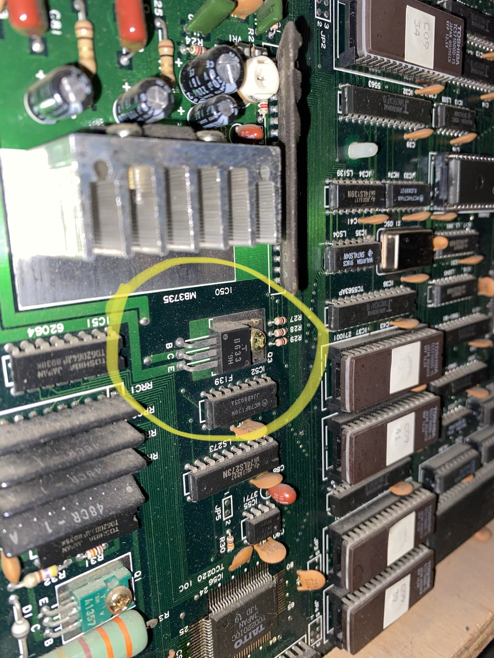
Originally I tracked this down to transistor Q3 which is a D633 NPN - circled in yellow.
I tested the old Q3 transistor with my multimeter in diode mode and got really low values - here are my new vs. old values. (out of circuit)
New Base to Emitter - .793
Old - .633
New Base to Collector - .628
Old - .618
New Emitter to Base - 2.685
Old - OL
New Collector to Base - OL
Old - OL
New Collector to Emitter - OL
Old - .020
This ended up being only part of the problem as the base of the transistor was connecting to ground so I traced it's path and it actually jumps from the bottom side of the board to the top - seems strange but maybe some way of saving PCB space or some other good reason.?
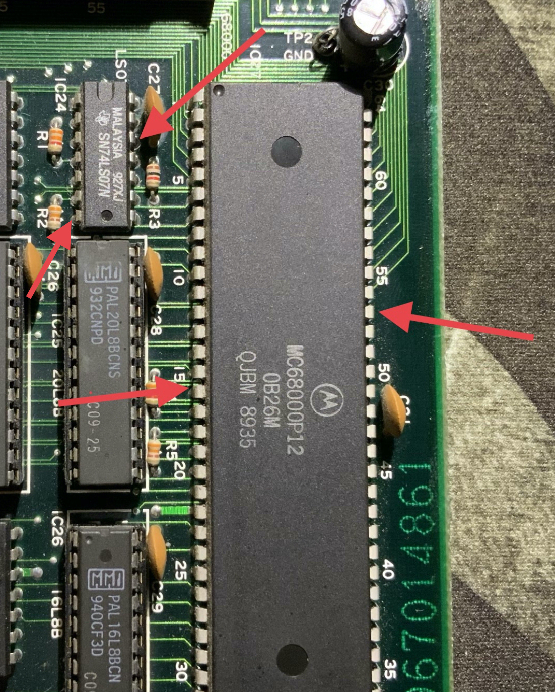
The trace ends up on the far side of the board near the Moto 68000 on the 'E' side of the CPU board connected to a TI SN74LS07N on pin 12 - seen here next to the Moto 68000.
The TI SN74LS07N is a driver for high voltage indicators and lamps... like for a motor!
https://html.alldatasheet.com/html-pdf/27979/TI/SN74LS07N/23/1/SN74LS07N.html
Once pulled out of the circuit there was still continuity between pin 12 and 7 (ground) on the old TI SN74LS07N, meaning this IC was shorted and so I replaced it.
Before connecting everything back up you should sanity check the AUX power boards -?
Both of the AUX power boards are fed VAC from the auxiliary power supply transformer, there are two separate windings on the transformer (I’m assuming they are separate so the Audio board gets less voltage): one is for the Audio AUX power board and the other for the Motor AUX power board - this passes through a bridge rectifier to convert to VDC and then passes though a largish smoothening / filter cap.
For the Audio AUX power supply - I’m seeing about +17 VCD, schematics say I should be seeing +13 VCD.
For the Motor AUX power supply - I’m seeing about +27 VCD, schematics say I should be seeing +24 VDC.
A little high but I’m assuming this is slightly inaccurate due to the crappy multimeter I’m currently using, my ‘good’ multimeter is on the fritz.?
The P3 (motor control) connector that plugs into the CPU board is pinned like this -
1: Red/White - supply from AUX power board (+24 VDC)
2: Black/White - supply from AUX power board (+24 VDC)
3: NC
4: Orange/Red - directly connected to motor
5: Orange/Red - directly connected to motor
The CPU board controls the switch logic and connects pins 1 + 2 to pins 4 + 5 and the motor turns on.
Please also double check the orientation of the P3 (motor control) header connector - ?
The diagram stapled to the inside of the cabinet shows the P3 (motor control) header connector with pin 1 at the top and pin 5 at the bottom, while on the CPU board pin 5 is at the top and pin 1 is at the bottom.


If you reverse this you will instantly blow the 3A slow-blow fuse on the Motor AUX power supply and/or cause more damage to the CPU board.
From top to bottom it should be -
Top -
Red/White
Black/White
NC
Orange/Red
Orange/Red
Bottom -
Parts needed for repair -
D633 Transistor (NPN)
TI SN74LS07N IC
Elysiom2020-11-27 03:53:49
Initial diagnosis: the 3A slow-blow fuse on the Motor AUX power supply was blown - I replaced it and the shaker motor would just run constantly / stuck ‘on’ when the game was powered on.
Originally I tracked this down to transistor Q3 which is a D633 NPN - circled in yellow.
I tested the old Q3 transistor with my multimeter in diode mode and got really low values - here are my new vs. old values. (out of circuit)
New Base to Emitter - .793
Old - .633
New Base to Collector - .628
Old - .618
New Emitter to Base - 2.685
Old - OL
New Collector to Base - OL
Old - OL
New Collector to Emitter - OL
Old - .020
This ended up being only part of the problem as the base of the transistor was connecting to ground so I traced it's path and it actually jumps from the bottom side of the board to the top - seems strange but maybe some way of saving PCB space or some other good reason.?
The trace ends up on the far side of the board near the Moto 68000 on the 'E' side of the CPU board connected to a TI SN74LS07N on pin 12 - seen here next to the Moto 68000.
The TI SN74LS07N is a driver for high voltage indicators and lamps... like for a motor!
https://html.alldatasheet.com/html-pdf/27979/TI/SN74LS07N/23/1/SN74LS07N.html
Once pulled out of the circuit there was still continuity between pin 12 and 7 (ground) on the old TI SN74LS07N, meaning this IC was shorted and so I replaced it.
Before connecting everything back up you should sanity check the AUX power boards -?
Both of the AUX power boards are fed VAC from the auxiliary power supply transformer, there are two separate windings on the transformer (I’m assuming they are separate so the Audio board gets less voltage): one is for the Audio AUX power board and the other for the Motor AUX power board - this passes through a bridge rectifier to convert to VDC and then passes though a largish smoothening / filter cap.
For the Audio AUX power supply - I’m seeing about +17 VCD, schematics say I should be seeing +13 VCD.
For the Motor AUX power supply - I’m seeing about +27 VCD, schematics say I should be seeing +24 VDC.
A little high but I’m assuming this is slightly inaccurate due to the crappy multimeter I’m currently using, my ‘good’ multimeter is on the fritz.?
The P3 (motor control) connector that plugs into the CPU board is pinned like this -
1: Red/White - supply from AUX power board (+24 VDC)
2: Black/White - supply from AUX power board (+24 VDC)
3: NC
4: Orange/Red - directly connected to motor
5: Orange/Red - directly connected to motor
The CPU board controls the switch logic and connects pins 1 + 2 to pins 4 + 5 and the motor turns on.
Please also double check the orientation of the P3 (motor control) header connector - ?
The diagram stapled to the inside of the cabinet shows the P3 (motor control) header connector with pin 1 at the top and pin 5 at the bottom, while on the CPU board pin 5 is at the top and pin 1 is at the bottom.
If you reverse this you will instantly blow the 3A slow-blow fuse on the Motor AUX power supply and/or cause more damage to the CPU board.
From top to bottom it should be -
Top -
Red/White
Black/White
NC
Orange/Red
Orange/Red
Bottom -
Parts needed for repair -
D633 Transistor (NPN)
TI SN74LS07N IC
Elysiom2020-11-27 03:53:49