I did this repair a while ago, it's the typical colour ram fault (or what appears to be a colour ram fault). I have at least 3 of these boardsets with these faults so thought it must be possible to repair at least one of them! I have another with some other sort of ram fault but thought colour ram should be easier.
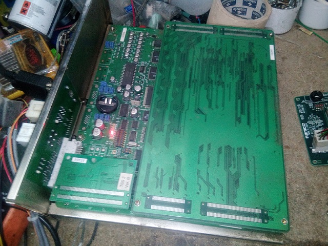
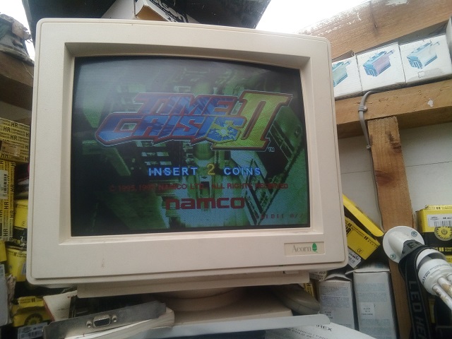
Boardset looks clean enough. I'd checked all these a while ago and wrote on a note on the cage that it's got a blue colour ram fault. Plugged it all in and after some faff with power cabling (i'm having to use a bodged in PC psu on an original loom from a twin cab) I got this on the screen:

Ignore the curvy image at the top, this Acorn monitor seems to do that with all Namco boards of this era for some reason, despite it being multisync! Probably just needs the sync tweaking but I can't get to the back of it easily (the adjustment might actually be inside the case, i've never really investigated!)
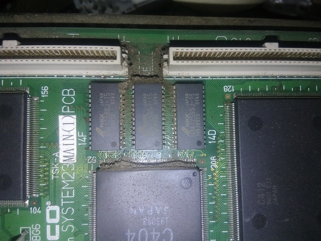
Anyway, I took this to be the blue colour ram, despite still having blue. Colours just seem to have gone haywire anyhow, the text is white which means all three colours are working - in a way, even if they're not where they 'should be'. Weird thing is, I always thought this was related to rgb mixing as it says PAL RGB, but if you turn on/off the dipswitch to ignore the boot up test, the game runs but with graphic faults - so these rams must have something to do with graphics code decoding or something as well. I have seen these rams actually affect the colours you'd think they're related to on the test, so I assume it's all down to how the RAM fails. Despite the board looking clean on top, it's a bit dusty underneath the rom board. I'd say it could've been static-y fingers caused the failure, but those long rom sockets would stop that and looking at the dust that's the side where the cage cooling fan is, so I suppose eventually the dust builds up and causes problems that the cooling fan can't prevent.
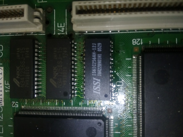
Cleaned most of the dust away. I don't like surface mount soldering at all, and despite having a hot-air station i've never got to grips with it so I just got the Chipquik on it. Removed the chip at 14D. Cleaned the area with isopropyl alcohol.

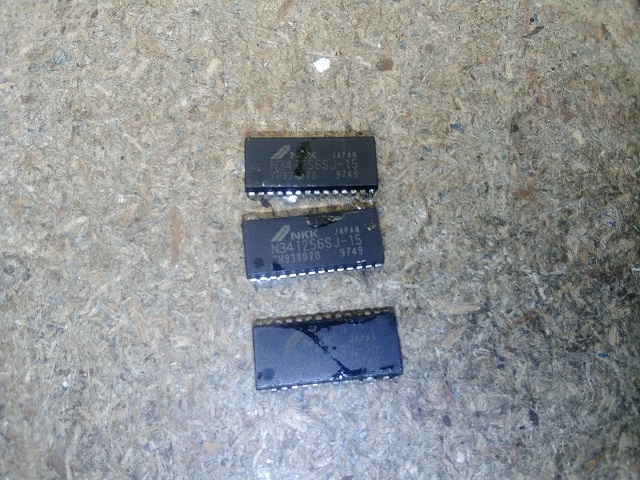
I'd bought some rams on eBay beforehand, so I had 10 of these to hand. They're 12ns so quicker than the originals and should work fine.

Ok, so eventually I got this soldered on nice and square and made sure (as far as I could tell) that all legs were connected and there were no legs soldered together.
Switched on and got this on the screen:

Seems worse than before! What's that telling me?
 That I haven't got all the legs connected on the new chip or that there's other chips that are bad? After the amount of time it took me to solder the chip on, I was starting to get a bit wound up to be honest, so decided to just remove the others to save a lot of messing about. As one had gone, these may have gone as well, or if they hadn't, as one had gone already they may go at some point soon.

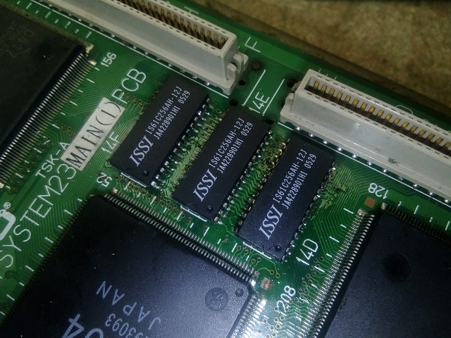
Got the others soldered on:
I still had errors on startup, so probably 15 minutes to half an hour of resoldering and testing with the boot sequence (and much swearing) later, I got this, much to my relief:
I left it on test for over an hour and it was fine. After all the messing about it wasn't that hard of a fix, and if I was better at surface mount soldering it would've gone fairly easy I expect, probably should've just gone and replaced all three in one go, but it is what it is.
Here's the guilty party:
It does give me hope for the other boardsets I have with similar PAL RGB ram faults, but I won't be doing them for a while! If they were through-hole chips I wouldn't have minded so much, these SOJ chips with the little curled under legs nearly drove me up the wall trying to get them all soldered properly!

Boardset looks clean enough. I'd checked all these a while ago and wrote on a note on the cage that it's got a blue colour ram fault. Plugged it all in and after some faff with power cabling (i'm having to use a bodged in PC psu on an original loom from a twin cab) I got this on the screen:
Ignore the curvy image at the top, this Acorn monitor seems to do that with all Namco boards of this era for some reason, despite it being multisync! Probably just needs the sync tweaking but I can't get to the back of it easily (the adjustment might actually be inside the case, i've never really investigated!)
Anyway, I took this to be the blue colour ram, despite still having blue. Colours just seem to have gone haywire anyhow, the text is white which means all three colours are working - in a way, even if they're not where they 'should be'. Weird thing is, I always thought this was related to rgb mixing as it says PAL RGB, but if you turn on/off the dipswitch to ignore the boot up test, the game runs but with graphic faults - so these rams must have something to do with graphics code decoding or something as well. I have seen these rams actually affect the colours you'd think they're related to on the test, so I assume it's all down to how the RAM fails. Despite the board looking clean on top, it's a bit dusty underneath the rom board. I'd say it could've been static-y fingers caused the failure, but those long rom sockets would stop that and looking at the dust that's the side where the cage cooling fan is, so I suppose eventually the dust builds up and causes problems that the cooling fan can't prevent.
Cleaned most of the dust away. I don't like surface mount soldering at all, and despite having a hot-air station i've never got to grips with it so I just got the Chipquik on it. Removed the chip at 14D. Cleaned the area with isopropyl alcohol.
I'd bought some rams on eBay beforehand, so I had 10 of these to hand. They're 12ns so quicker than the originals and should work fine.
Ok, so eventually I got this soldered on nice and square and made sure (as far as I could tell) that all legs were connected and there were no legs soldered together.
Switched on and got this on the screen:
Seems worse than before! What's that telling me?
Got the others soldered on:
I still had errors on startup, so probably 15 minutes to half an hour of resoldering and testing with the boot sequence (and much swearing) later, I got this, much to my relief:
I left it on test for over an hour and it was fine. After all the messing about it wasn't that hard of a fix, and if I was better at surface mount soldering it would've gone fairly easy I expect, probably should've just gone and replaced all three in one go, but it is what it is.
Here's the guilty party:
It does give me hope for the other boardsets I have with similar PAL RGB ram faults, but I won't be doing them for a while! If they were through-hole chips I wouldn't have minded so much, these SOJ chips with the little curled under legs nearly drove me up the wall trying to get them all soldered properly!
