

I was on a bit of a Konami roll (2 x Circus Charlie PCBs & 3 x Hyper Olympic PCBs repaired) so I decided to investigate a couple of Time Pilot PCBs I'd had in storage but had developed faults.
This is just Time Pilot 1 (TP2 has a sound fault coming from the main PCB I have to track down).
Time Pilot 1 would boot to black screen. There was something holding it back. I initially discovered the chip at A2 (a 74ls138 I think) was faulty and after replacing it I momentarily got the white grid pattern (albeit corrupted) and the PCB died again, for a long time. I knew the problem was clock related but I just couldn't get the bottom of it.
I'd been trying to repair this for what seemed like an age when I stumbled across a signal from the custom IC of pin 2 from F5 after going over the clock circuit about half a dozen times.

The schematic showed that the signal left pin 2 of F5 went into an ls368 at G4 and then onto the custom IC C2 pin 10 at C3. I noticed that the signal from F5 was a feint logic low, when it hit G4 it was also feint logic low but when it hit IC2 at C3 it was feint logic high. The custom had tested good so this was perplexing since nothing else was supposedly on that line. I inspected the board looking for a bridge but found nothing. What I did find though (and what was an extreme PITA and annoying) was that the line was also attached to pins 3 & 4 of IC A12 (74ls10) and pin 1 of IC E10 (custom). I had missed this further up the logic diagram (i.e. signal G1).
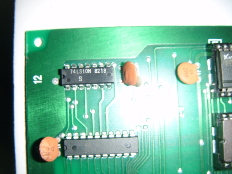
A12 (74ls10)

IC8 at E10
Replaced the 74ls10 at A12 and the pull up to high on custom C3 is now cleared and the board is fully operational. The schematic makes it look like that G1 signal comes after pin 2 of F5 but it actually comes in after pin 2 of G4 giving a considerable throw on things.
jonhughes2020-10-05 06:51:24
This is just Time Pilot 1 (TP2 has a sound fault coming from the main PCB I have to track down).
Time Pilot 1 would boot to black screen. There was something holding it back. I initially discovered the chip at A2 (a 74ls138 I think) was faulty and after replacing it I momentarily got the white grid pattern (albeit corrupted) and the PCB died again, for a long time. I knew the problem was clock related but I just couldn't get the bottom of it.
I'd been trying to repair this for what seemed like an age when I stumbled across a signal from the custom IC of pin 2 from F5 after going over the clock circuit about half a dozen times.
The schematic showed that the signal left pin 2 of F5 went into an ls368 at G4 and then onto the custom IC C2 pin 10 at C3. I noticed that the signal from F5 was a feint logic low, when it hit G4 it was also feint logic low but when it hit IC2 at C3 it was feint logic high. The custom had tested good so this was perplexing since nothing else was supposedly on that line. I inspected the board looking for a bridge but found nothing. What I did find though (and what was an extreme PITA and annoying) was that the line was also attached to pins 3 & 4 of IC A12 (74ls10) and pin 1 of IC E10 (custom). I had missed this further up the logic diagram (i.e. signal G1).
A12 (74ls10)
IC8 at E10
Replaced the 74ls10 at A12 and the pull up to high on custom C3 is now cleared and the board is fully operational. The schematic makes it look like that G1 signal comes after pin 2 of F5 but it actually comes in after pin 2 of G4 giving a considerable throw on things.
jonhughes2020-10-05 06:51:24

