Hello,
I'm trying to make a cable that connects into my small Hitachi crt monitor - for my Taito Field Goal cab.
Things are going well, I've got the plug, the pins and have identified which are the red,green,blue,sync and ground pins.
Just power to go.
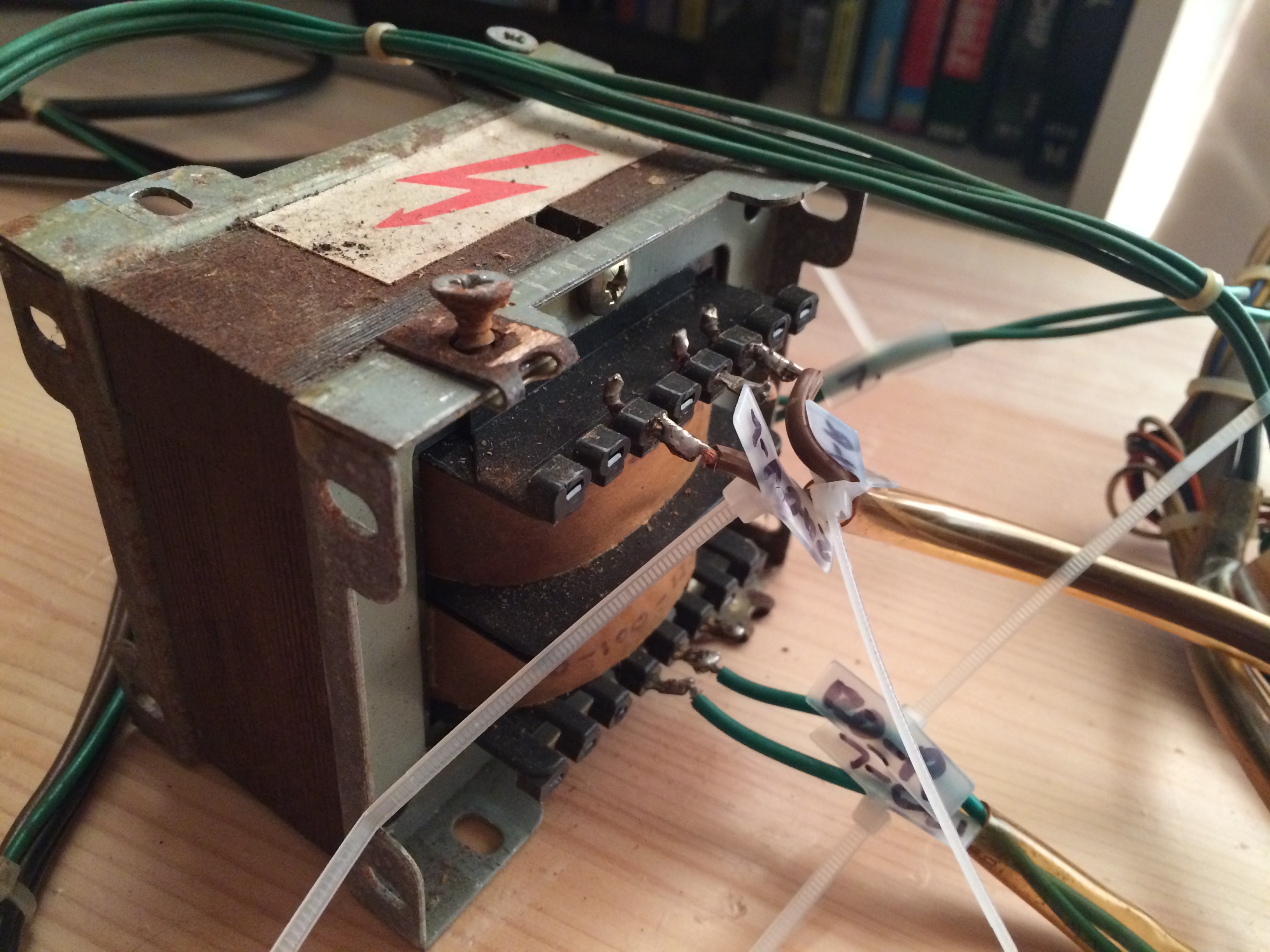
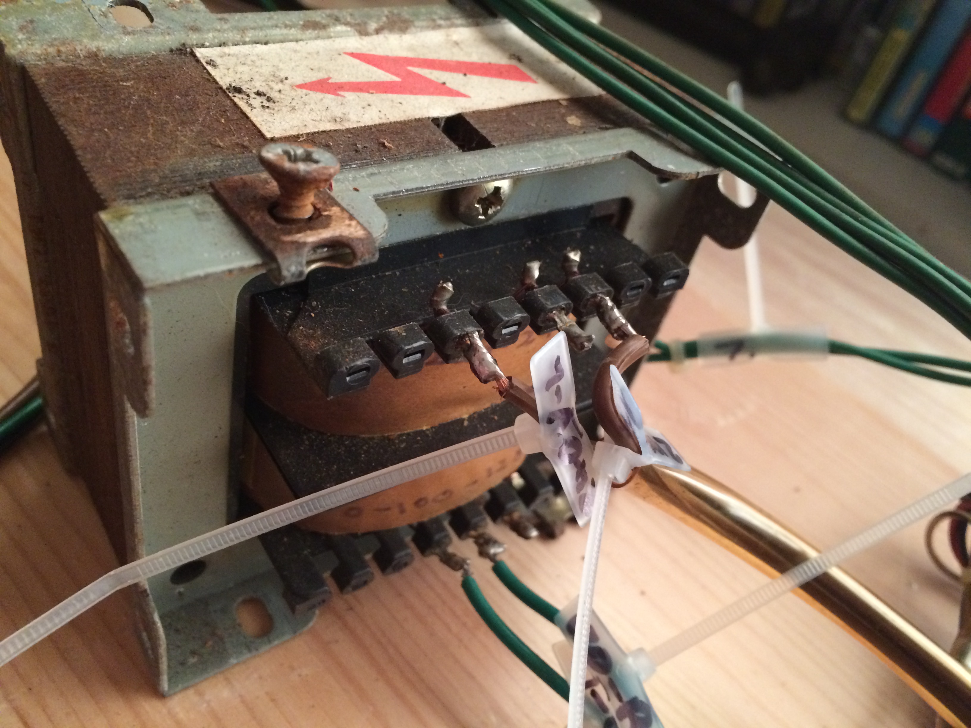
The monitor takes 120V from the transformer, but where it connects on the chassis, I cant work out which is + and which is -
Does it matter which way round I connect the 2x 120V cables to the monitor (via the plug) ?
Can anyone help - advice would be appreciated as this has me stumped and I don't want to blow it all up now")
Here's some pictures:
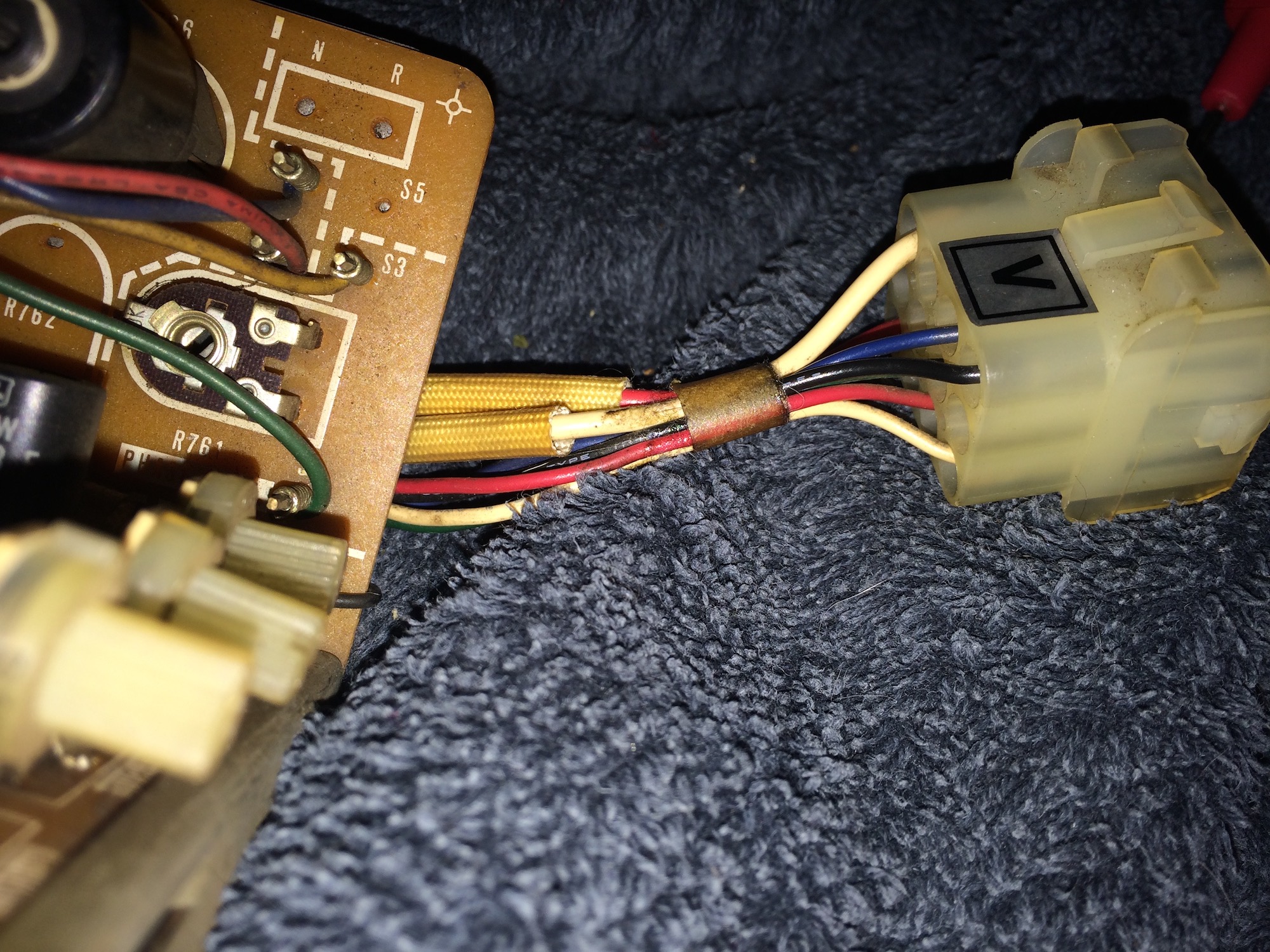
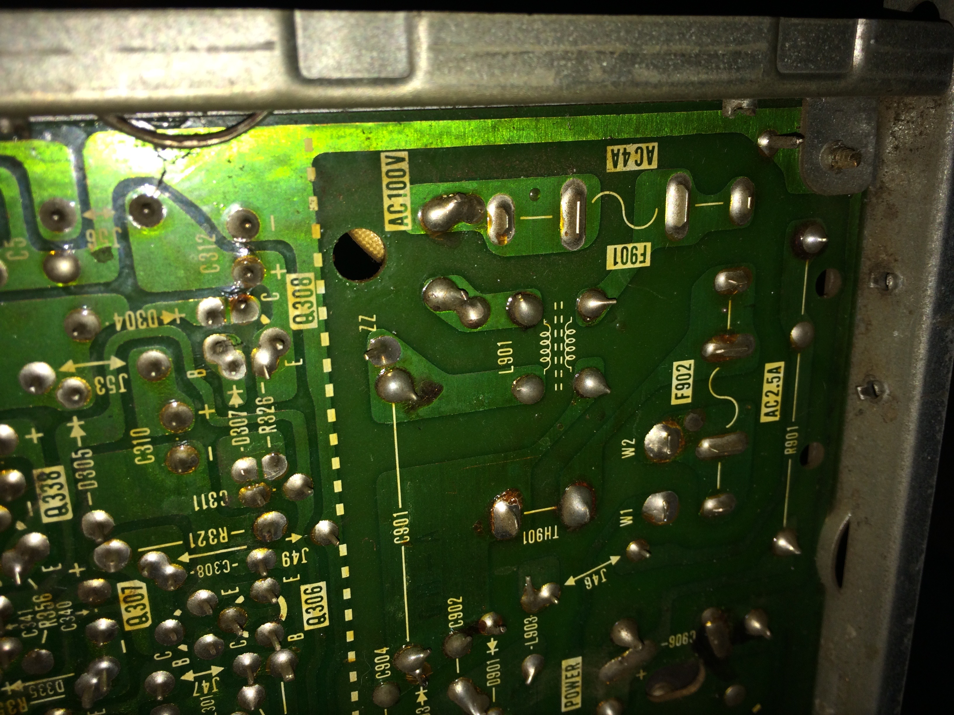
Edge of monitor chassis showing the monitors plug. (My new plug /cable will plug into this one)
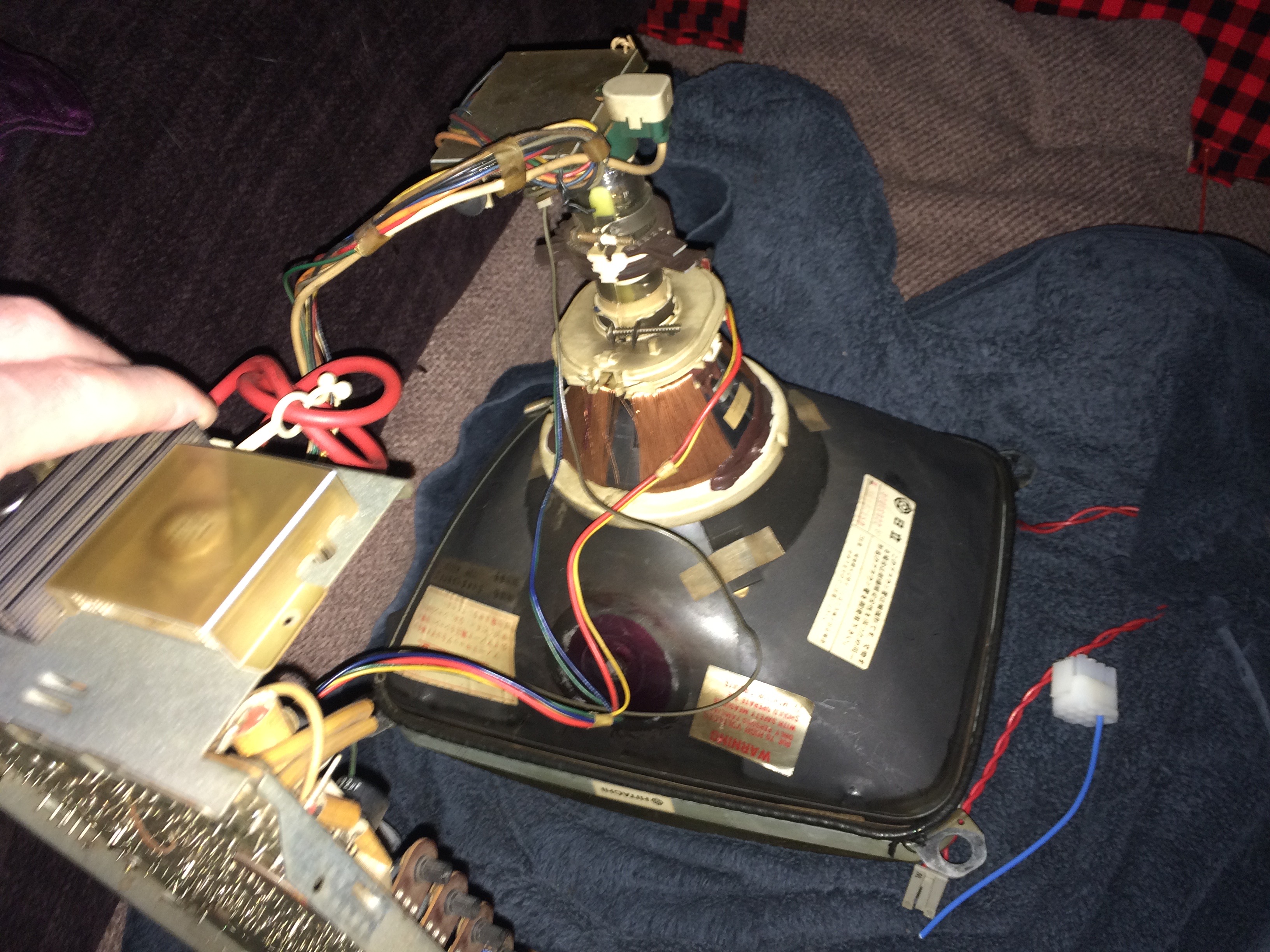
The 2 power cables connect to the monitor chassis in the photo below, the dirty white braided cover cables (inside the cable covers: 1 is red, 1 is white):


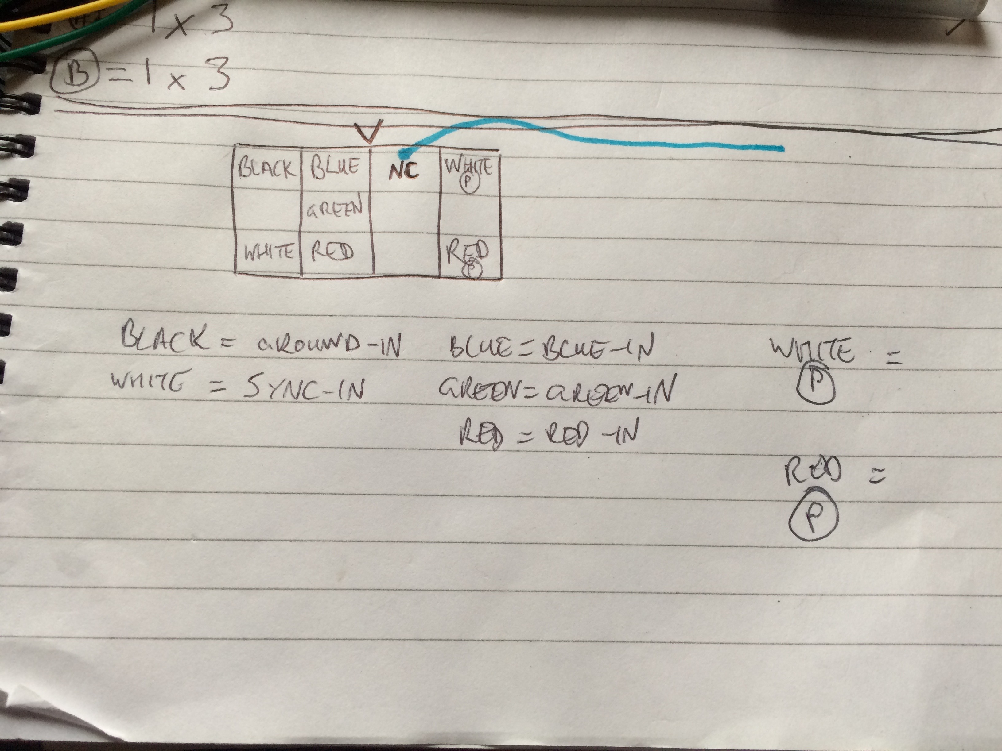
I made this diagram while using multimeter to continuity test where each pin went, as if you're looking into the plug that comes from the monitor:
Cheers,
Johnny
I'm trying to make a cable that connects into my small Hitachi crt monitor - for my Taito Field Goal cab.
Things are going well, I've got the plug, the pins and have identified which are the red,green,blue,sync and ground pins.
Just power to go.
The monitor takes 120V from the transformer, but where it connects on the chassis, I cant work out which is + and which is -
Does it matter which way round I connect the 2x 120V cables to the monitor (via the plug) ?
Can anyone help - advice would be appreciated as this has me stumped and I don't want to blow it all up now
Here's some pictures:
Edge of monitor chassis showing the monitors plug. (My new plug /cable will plug into this one)
The 2 power cables connect to the monitor chassis in the photo below, the dirty white braided cover cables (inside the cable covers: 1 is red, 1 is white):
I made this diagram while using multimeter to continuity test where each pin went, as if you're looking into the plug that comes from the monitor:
Cheers,
Johnny