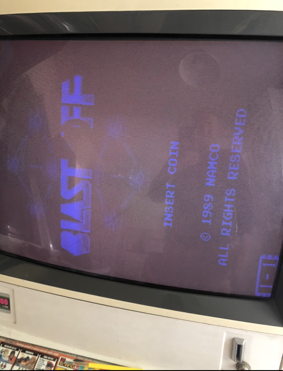
Blast off system 1 namco , only blue,

Retroman839

Senior Member
vacBacker
Feedback
13 (100%)
Credits
7,475CR
I have this system 1 namco
Blast off,,
It shows blue only but with no real luminescence,

Have tried tying pin 1 to pin 14, ground to vid ground,
Still no difference
04B682A5-F44F-4FAB-8DA3-0148417328C0.jpeg
1FB4E3A8-EAAC-4300-8433-CEA5C7D344D2.jpeg
 

John Bennett

Senior Member
vacBacker
Feedback
10 (100%)
Credits
5,090CR
System1.JPG


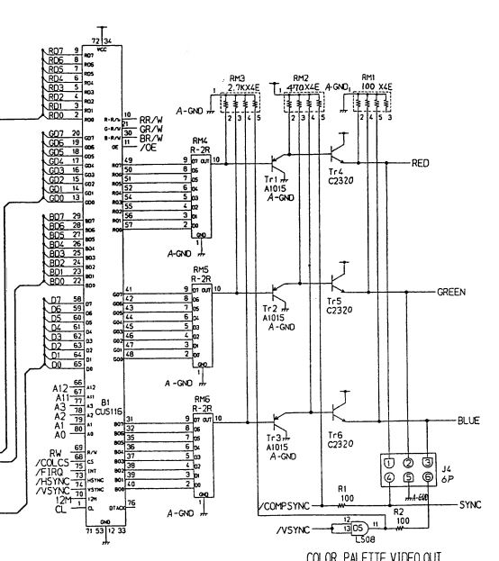
I'd place my bets on the rightmost NPN transistors being damaged so they can't pull the signal up to anywhere near 5V.

I can't think of anything you could easily test though, well not without a scope.
 

Retroman839

Senior Member
vacBacker
Feedback
13 (100%)
Credits
7,475CR
Thanks for the schematic john..

I was thinking both transistors in the red & green as total loss of signal.
And poss one of them is still working a bit in the blue as it’s a weak signal..

Like we were saying in regards to using scart tv for jamma ..
It is possible if this board was connected to a tv it could cause over drive in the rgb circuit causing burn out on the transistors?

I was thinking of just changing all six ..
9EC05552-BE23-4B46-82DD-2BB470762215.jpeg
Retroman8392022-06-11 21:45:34
 

Retroman839

Senior Member
vacBacker
Feedback
13 (100%)
Credits
7,475CR
John Bennett said:
<span style="font-size: 12px;">
System1.JPG
</span>
<span style="font-size: 12px;">
</span>

<span style="font-size: 12px;">I'd place my bets on the rightmost NPN transistors being damaged so they can't pull the signal up to anywhere near 5V. </span>

<span style="font-size: 12px;">I can't think of anything you could easily test though, well not without a scope.</span>

Is Rm1. Rm2. & Rm3. The resistor banks?
Transistors more Likely to fail first?
 

John Bennett

Senior Member
vacBacker
Feedback
10 (100%)
Credits
5,090CR
These are an interesting circuit as they've got a LOT of drive power.
There's no series resistors on the RGB circuit to limit the power and those NPNs can deliver a fair bit of current compared to boards that just use 74xx devices on the output.

So if you did mis-wire it (like connecting to a TV with little or no resistors), then it could pull quite a lot of current and knack the transistors. The TV would be very over-saturated too (been there with similar boards and scratched my head decades ago before I worked out about proper SCART wiring).

It's very, very unlikely to be the R2R resistor networks, they don't see much of the action as they're before things get amplified.

The transistors do die on these for sure though.
 

Retroman839

Senior Member
vacBacker
Feedback
13 (100%)
Credits
7,475CR
Thanks for the npn Heads up

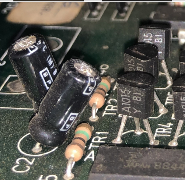
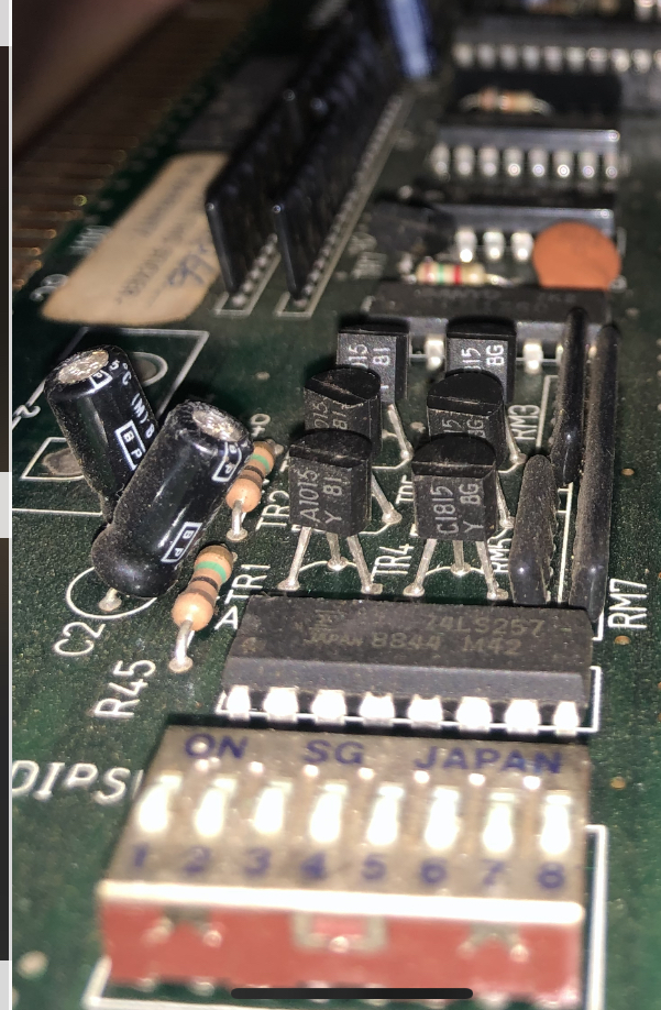
On my board the transistors are c1815, the schematic has c2320’s

Guessing this is system 1 but possibly different game?
So I should stick to c1815’s & A1015’s

Looking forward to this little repair..

As after board video repair
I will burn some roms for some other system 1 games

Are the letters and numbers that follow under on the transistors important?
Or not important Y 8G Y8I ?
Just batch /date code?

Retroman8392022-06-11 22:45:29
 

John Bennett

Senior Member
vacBacker
Feedback
10 (100%)
Credits
5,090CR
Yeah, go with as close as possible to the original.
I don't fully know what the codes mean, but looking at the datasheet, there's a note at the bottom of page 1 and it suggests Y might an HFE of 120-240
2SC1815 pdf, 2SC1815 Description, 2SC1815 Datasheet, 2SC1815 view ::: ALLDATASHEET :::

The HFE/gain is very important - it sets how much the transistors amplify, so get it wrong and it'll be too dim, or saturated (and you'd have to do all 3 colours too, or it'd never look right). Happy to browse datasheets if you find something to try.

I'd say the probability of failure is greater as you move right, so the final stage transistors are more likely to be dead than A1015's.

There's 2 stages of transistors to chain-up the gain/current from the tiny amount that flows in the resistor arrays.

 

Retroman839

Senior Member
vacBacker
Feedback
13 (100%)
Credits
7,475CR
This looks good found a seller selling them together for hifi hi amplification

A1015 Silicon (PNP), C1815 (NPN), complimentary, TO92, 50v 150mA
Silicon Epitaxail Type (for Audio Frequency General Purpose Amplifier Applications and discharge display drivers) ...

Do you think these look ok

A1015 Silicon (PNP), C1815 (NPN?

Possibly then the blue 1015 first transistor is ok..

Retroman8392022-06-11 23:51:15
 

Monstermug

Active member
Feedback
23 (100%)
Credits
1,807CR
On the cus116 Is pin 10,21 and 11 pulsing like it is on 30? If its is then check pin 10 on the resistor pack,if its not the resistor pack then its the transistors. I dont think there are any caps on the video circuit as it outputs ttl sync irrc. And if its not the transistors then its your monitor
smiley9.gif


If its not your monitor you might as well sell it to me cheap
smiley17.gif
 

Monstermug

Active member
Feedback
23 (100%)
Credits
1,807CR
I often get these namco sys 1 boards with all these transistors squashed. I have to straighten them out. Thought you would have checked them first as they are first thing on the rgb lines.
 

Retroman839

Senior Member
vacBacker
Feedback
13 (100%)
Credits
7,475CR
Yeh my scope is packed
Away I could get it out,
But I was thinking
Of changing the transistors as it seems most likely
Suspects ..
Monitor is good been using it
today
 

Retroman839

Senior Member
vacBacker
Feedback
13 (100%)
Credits
7,475CR
John Bennett said:
Yeah, go with as close as possible to the original. 
I don't fully know what the codes mean, but looking at the datasheet, there's a note at the bottom of page 1 and it suggests Y  might an HFE of 120-240
2SC1815 pdf, 2SC1815 Description, 2SC1815 Datasheet, 2SC1815 view ::: ALLDATASHEET :::

The HFE/gain is very important - it sets how much the transistors amplify, so get it wrong and it'll be too dim, or saturated (and you'd have to do all 3 colours too, or it'd never look right). Happy to browse datasheets if you find something to try.

I'd say the probability of failure is greater as you move right, so the final stage transistors are more likely to be dead than A1015's.

There's 2 stages of transistors to chain-up the gain/current from the tiny amount that flows in the resistor arrays.

Right yes I see…
Y =. Hfe. 120-240. G =200 -400

I need to get value Y then got it.

This transistor is further divided into four groups according to the DC current gain, O, Y, G, and L and has 140, 240, 400 and 700 hfe DC current gain respectively.

Data sheet says saturation is 1.1v. This voltage is suitable for the arcade chassi..
Where as tv scart requires 5v ? And it is the draw from the tv that causes the over drive killing the transistor ?

And because I am learning
I will test them out of circuit by measuring the Hfe and compare them all
Against the replacements…

I should
Then get an idea at least that before I solder the new ones back in
That I’m changing bad for good.
Retroman8392022-06-12 08:32:33
 

John Bennett

Senior Member
vacBacker
Feedback
10 (100%)
Credits
5,090CR
It could be that, or it's not about letters and they put coloured stripes on them if they have a higher gain (so presumably the ones we have would then be 70-240). Can't say I've looked, or even realised there were variants until I just looked.

It's not that base saturation voltage that matters - voltage is down to the circuit. When the input to the rightmost transistors are off, the R/G/B outputs will be pulled down to 0V by RM1 (and you get black on R/G/B)

As it gets current into the base (from the 'A' transistor), it'll multiply that current by HFE and start flowing current between the collector an emitter, acting as a pull-up on the R/G/B output ( and fighting RM1 and whatever monitor is connected, which will also have a resistor to ground).

It can pull right up to 5V, if you look at what's going into the collector. So at full drive it's capable of pulling the R/G/B to 5V with up to 150mA (in rough theory). If you wire that directly to a TV, then I don't think TVs fail if put 5V into their inputs, but it might cook the 75ohm resistors inside and the image will be massively washed-out. I can't see how it'll kill these transistors, mind you - they can do a fair whack of current.

John Bennett2022-06-12 08:27:17
 

Retroman839

Senior Member
vacBacker
Feedback
13 (100%)
Credits
7,475CR
Why then would you say they have or Likely have
Stopped functioning?

They fail from long usage
Or just perish over time?

I watched the documentary on transistors
And how the yanks wouldn’t share the secret with the Japanese..
And it used a particular metal for it to operate with out high failure..
Is this due to oscillation causing separation ? Retroman8392022-06-12 08:38:59
 

John Bennett

Senior Member
vacBacker
Feedback
10 (100%)
Credits
5,090CR
I’ll have to say I don’t know. Wiring it straight to a TV will pull twice the current, so maybe over time. Maybe someone shorted the RGB to ground once… hard to say.
Connecting the power supply backwards can wreck them (and the rest of the game!)

They don’t tend to just weaken, as far as I know (well not to the extent of having zero gain).

Or it’s not the transistors
smiley4.gif
. First thing to test though, I’d say
 

Phils Arcade

Senior Member
vacBacker
Feedback
10 (100%)
Credits
1,444CR
Not very often, but sometimes those resistor packs can get bent over, and someone straightens them cracking the case. Hard to spot, but have seen it happen.

Close visual inspection, and maybe gentle push just to check. A hairline crack would stop it in its tracks.
 

Retroman839

Senior Member
vacBacker
Feedback
13 (100%)
Credits
7,475CR
Will have a look at resistors packs
For any signs of cracking.

I’m going to look at the transistors I bought
Year or so ago for this little project.
To see if I managed to buy the correct ones.
If so I may change them tomorrow.
And test.

Otherwise I will need to order new
 
Top