capacitor zapping method to clear CRT shorts?

andyJay

User
vacBacker
Credits
98CR
well looks like my crt tube is buggered, as the blue cathode is shorted to the spark gap, caused by the neckboard flyback wire coming lose and doing god knows what..
read up on the zapping method which involves charging a 47uf 250V film cap and discharging it between the sparkgap and then the blue cathode to (hopefully) clear the short.

anyone tried this or would it be worth it (and maybe easier) to find someone with a rejuvenator, if that would even work on a sparkgap short?

thanks guys
 

Georgian2

Active member
Feedback
12 (100%)
Credits
1,868CR
well looks like my crt tube is buggered, as the blue cathode is shorted to the spark gap, caused by the neckboard flyback wire coming lose and doing god knows what..
read up on the zapping method which involves charging a 47uf 250V film cap and discharging it between the sparkgap and then the blue cathode to (hopefully) clear the short.

anyone tried this or would it be worth it (and maybe easier) to find someone with a rejuvenator, if that would even work on a sparkgap short?

thanks guys
Is that sparkgap on the PCB like copper etched on the PCB or an component soldered on?
 

andyJay

User
vacBacker
Credits
98CR
i dont sadly, tried to look up the model number on tubular,its a A51LZM10X20 , doesnt show , but the A51L******* are all cr-23's. im using an adapter i got from aussie arcade on another forum.
theres some pics of the adapter here: https://www.ukvac.com/forum/threads/monitor-swap-for-k7000-2-dag-wires-on-donor-crt.91878/

tried some trouble shooting from grant and MKL , even desoldering R202 for the blue gun and its still blue. so much conflicting info on which pin is which on the cr-23 on different forums , some say the last two pins are blue and a sparkgap, others say its heater 2 (H2) and last is blue cathode, but that conflicts with what this adapter has printed on the board .

looking at this image , pin 11 and 12 are shorted on the actual tube itself:
img_20260903_165836-jpg.63934


just so much conflicting info, so if youve any ideas Georgian that would be great

cheers
 

Georgian2

Active member
Feedback
12 (100%)
Credits
1,868CR
Phisical pin 11 on the CRT neck must be blue. No indea what pin 12 is. You must look on your CRT adapter where does the pin 12 go. Best thing you can try is to find a way to isolate the pin 12. you may make a cut/gap on that adapter PCB near the solder joint for the said pin. (Make sure you know what you are doing and don't blame me if you make an msitake)

Isolating the pin12 should solve your problem.

Here is the pinout for the crt neck pins.

https://ia803201.us.archive.org/7/items/manual_MD20Q41_SM_TOSHIBA/MD20Q41_SM_TOSHIBA.pdf
 

andyJay

User
vacBacker
Credits
98CR
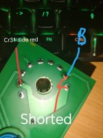
Thanks Georgian, pin 12 goes to ground on the adapter , i can get continuity on it from the dag wire on the neck board, and it looks like its tied to the sparkgap and pin 4, which is tied to RED on the cr31 side!

MKL did a post about this on another forum:

https://forums.arcade-museum.com/th...erest-cr31-chassis-to-cr23-tube.537996/page-2

in this case he suggested cutting the link to pin 4 , i dont get why red would be tied in with the sparkgap?

really appreciate the help, thanks
 

andyJay

User
vacBacker
Credits
98CR
1000066760.jpg
a picture speaks a thousand words.. sorry for the crap diagram,but i think you get the gist
 
Last edited:

andyJay

User
vacBacker
Credits
98CR
Thanks Georgian, heard back from MKL he says that G1 (red) on the k7000 is OK to be grounded via the spark gap, so I'll cut that trace for pin 12 off tonight and let you know how it goes, these adapters are a nightmare, seems chopper79 on here had similar problems with his hantarex..
Cheers again
 

tb2000

Active member
Feedback
4 (100%)
Credits
3,481CR
I think these possibly use a neck socket that's not the same as the original Hanty or WG 10 pin. There's pins that aren't required if I remember correctly, so they need to be snipped off so they don't solder in. I replaced an iffy neck socket with one similar to this on a Hantarex neckboard and had a colour stuck on, it also burnt out a resistor on the neckboard if I remember correctly. Replaced the resistor and the neck socket with a used original and it was fine.
 

andyJay

User
vacBacker
Credits
98CR
Cheers tb, turns out talking with MKL these tubes have pin 11 and 12 tied,and pin 12 on this socket board does definetly connect with the spark gap and g1, good news is the k7000 g1 pin should be connected to the spark gap so that's one less thing to cut.. I'll keep my eyes open for any dodgy resistors on the neck board if killing the trace for pin 12 doesn't solve the problem
 

andyJay

User
vacBacker
Credits
98CR
Cut and took out the socket pcb leg for pin 12 and:
Excuse the pun, but I'm shocked...
Thanks for all the help guys, can't tell you how happy and relieved I am.. Colours are gorgeous, even better than my old 19" burn free philips!
1000066787.jpg1000066791.jpg
 
Top