Jamma harness ground connections?

kingtreelo

Active member
vacBacker
Feedback
18 (100%)
Credits
1,556CR
Hi, so i need to tie all my ground connections together on my jamma harness and other than running a little wire, is there an easier way to do this?

I would guess there is a connector that you can put one ground wire in that bridges the 2/4 pins?

Does something like that exist, and if so, what is it called?
 

John Bennett

Senior Member
vacBacker
Feedback
10 (100%)
Credits
5,020CR
The idea really is to have separate cables back to the PSU for every ground pin, and in the same way have separate cables for every 5V, 12V and -5V pin.
This reduces the voltage drop across the cables.
Otherwise you risk different voltages being applied to different games, depending on their power draw, unless you're going to twiddle the PSU dial every time.
 

favouredson

Super Star
vacBacker
Credits
1,256CR
As JB stated, the more the merrier.
If your cabinet loom is properly wired it will also make up for deficiencies in any JAMMA adaptors you might use.
 

kingtreelo

Active member
vacBacker
Feedback
18 (100%)
Credits
1,556CR
so ive had a look today and cant see any spare wires at all to hook up to the harness, i was expecting to see a few ground wires on the loom that were loose but nothing...

any ideas?
 

favouredson

Super Star
vacBacker
Credits
1,256CR
Ideally, you would add wires from the PSU to the connector.
If you are unable/unwilling to do this then you could always do a bodge and make up a JAMMA to JAMMA adaptor with all the ground pins interconnected.
 

kingtreelo

Active member
vacBacker
Feedback
18 (100%)
Credits
1,556CR
Ideally, you would add wires from the PSU to the connector.
If you are unable/unwilling to do this then you could always do a bodge and make up a JAMMA to JAMMA adaptor with all the ground pins interconnected.
could i not just connect the grounds that are already wired to the other pins?

im not even 100% this is going to fix my problem but its worth a shot
 

BigP_BigP

Newbie
Feedback
1 (100%)
Credits
112CR
could i not just connect the grounds that are already wired to the other pins?

im not even 100% this is going to fix my problem but its worth a shot
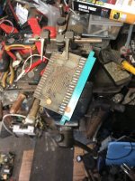
Totally agree with all the above posts. Commonly grounding issues stem from poor quality wire (too little copper). This is a particular issue on some of the eBay/Aliexpress JAMMA harnesses. I restored(?) a Chinese clone blast city a year or so ago to make a dedicated DDPDOJ cabinet. In doing this I had to totally remove the gnd and 5v wires (apart from the thinner button grounds) and upgrade the wire thickness to 16awg. Typically the cheaper harnesses look like 18awg but when you cut the wire it only has the copper of a 20-24awg wire the thickness comes from the shielding. Something similar may help in this situation. (Excuse the cab pic post... any excuse)
 

Attachments

  • 20250701_173632 (1).jpg
    20250701_173632 (1).jpg
    84.2 KB · Views: 23

kingtreelo

Active member
vacBacker
Feedback
18 (100%)
Credits
1,556CR
so im revisiting this, had a busy few weeks, so are people suggesting i should have all 8 of my ground pins on the harness wired back to the PSU?

apologies if im being a bit stupid here, but im not sure how i would fit 8 wires onto the PSU single ground connection, really want to get this up and running with my pi2jamma rather than being limited to just the PCBs that came with them
 

qjuk

Active member
vacBacker
Feedback
50 (98%)
Credits
1,872CR
You don’t need 8 ground wires running back to the PSU.

I normally have 4 decent quality ground wires from the PSU to the JAMMA edge. 1 wire to connect both pins A+B, 1 wire to connect pins 1+2, 1 wire for pins 27+28 and 1 wire for pins e+f. I solder the ground wire in the middle between the 2 pins and cover with heat shrink tubing. You can also bend the JAMMA connector solder pins slightly towards each other to make to soldered bridge connection easier.
 

kingtreelo

Active member
vacBacker
Feedback
18 (100%)
Credits
1,556CR
You don’t need 8 ground wires running back to the PSU.

I normally have 4 decent quality ground wires from the PSU to the JAMMA edge. 1 wire to connect both pins A+B, 1 wire to connect pins 1+2, 1 wire for pins 27+28 and 1 wire for pins e+f. I solder the ground wire in the middle between the 2 pins and cover with heat shrink tubing. You can also bend the JAMMA connector solder pins slightly towards each other to make to soldered bridge connection easier.
so i have wires on about 4 or 5 of the pins, on all 3 of my jamma connectors(they are all identical harnesses and wires from the 80's), they seem pretty tightly crimped on, i just dont know where to begin to bridge them or take the current ones off and replace them with some sort of adapter that connects the earth to 2 of them at a time

the problem is that my wires are connected up to just one pin..and not both of them
 

qjuk

Active member
vacBacker
Feedback
50 (98%)
Credits
1,872CR
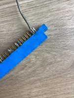
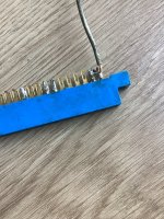
I’ve just pulled out a scrap connector and a scrap piece of wire to show you where I mean the wire is soldered (bridged) between the two pins.
IMG_7901.jpeg

A solder blob should bridge the two pins nicely.

Another technique is to strip the wire back a bit more so you have more of the copper exposed. Bend the copper end of the wire into an “L” shape. solder first on one pin, then the end onto the second pin.
IMG_7902.jpeg

Tidy up with some heat shrink tubing and you should be all good.
 

kingtreelo

Active member
vacBacker
Feedback
18 (100%)
Credits
1,556CR
i guess the worst thing that can happen is i will need to buy a new harness and wiring, which may be the easier option, i'll give the solder thing a crack and see how i get on
 

kingtreelo

Active member
vacBacker
Feedback
18 (100%)
Credits
1,556CR
so im going to bump this rather than start a new thread, i dont know how to remove the wires that are attached to the harness to do the above, i have seen some harnesses with 1 wire kind of split...anyway, i digress

so my plan is...and this is where i need help, i was going to buy some more wire and wire from the harness back to the PSU, but here is the cavaet, i was going to buy a bigger spade connector so i can feed more than one wire into it, as the GND on my new PSU has 4 already going into it.

i also have read i need 18AWG wire but upon looking, they dont seem to look anything like what i would expect them, so a pointer would be great on that as well

is the above plan doable or am i talking nonsense?

the biggest problem i think i have is that new PSUs only have one ground and not 2 like the older ones, otherwise the new wiring wouldnt be such a pain
 

BigP_BigP

Newbie
Feedback
1 (100%)
Credits
112CR
You are looking for 18awg or wire rated for between 7.5A and 10A.

You will need to desolder the wire from the existing JAMMA connector or use a new JAMMA connector. You can cut it a little before the connector and just desolder the bit left attached to the connector if that is easier.

As far as getting 2 wires to a single PSU GND you can either buy a crimp terminal big enough to safely crimp both wires together in the same terminal (can be difficult to find and get right) or stack two terminals on top of each other at the PSU (which can also be difficult to get right). This is definitely doable but getting it right can be difficult and I would advise using heatshrink over any crimp at the PSU end to help reinforce the crimp.
 

69er

Active member
Feedback
6 (100%)
Credits
1,650CR
At the PSU terminals , fitting two or more wires securely under the screw can be awkward, even difficult and look untidy.

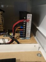
As suggested above here is a quick picture of crimped eye/fork end connectors in an assorted bag and a whole row of them in use on a retired switch mode power supply speedily salvaged pre cremation of something in the past? My lazy recovery method when burning a few at a time years ago…. The +5v has 5 wires on two crimp ends while the 0v ground has two each of 3 wires .. 2 wires in most of the others except the -5v (rarely used anyway)

If a wire is only partly trapped by the screw it actually reduces the diameter of the wire at that point and could warm up (just like a fuse) the whole wire need to conduct the current … is often why ground tabs on pcbs get hot - usually because only one or two edge connector pins have been used so YOU ARE on a sensible direction to spread the supply current to all available tabs.


If only one terminal is available on a replacement PSU the two black 3 wire eyelets could be attached from above and below to get the eye/fork end firmly under the terminal screw. (Otherwise too bulky from just one side?)

Also as @qjuk shows in pictures above if you are not confident or tidy with a soldering iron (I am not patronising here) just spend a bit of time practicing attaching wires to tabs on connectors and off again ? Secret is apply the iron to both the wire and tab to heat them equally then briefly introduce the solder to the tip of the hot iron and wire and tab … get a good smooth flow and withdraw the iron slowly away holding wire in place, as it cools job done ….. it is just an experience thing the more you try the easier it is .

Not enough hands ??? NEVER put solder in your mouth as a third hand … toxic !!!
Buy one of those twin crocodile clip wire holders often with a magnifying glass in the centre,,, they free up one hand so you can hold the solder and the iron easily?

 

Attachments

  • IMG_9308.jpeg
    IMG_9308.jpeg
    74.1 KB · Views: 15
  • IMG_9309.jpeg
    IMG_9309.jpeg
    95.4 KB · Views: 13

qjuk

Active member
vacBacker
Feedback
50 (98%)
Credits
1,872CR
im pretty sure i have 4 ground fork connectors already and remember it being a nightmare to get them to hold
Depending on the PSU you have, you might be able to put 2 of the fork connectors on one side and the other 2 on the opposite side.

A bit like what I’ve done here on one of my PSUs with the red +5v connectors…
IMG_7942.jpeg
 

69er

Active member
Feedback
6 (100%)
Credits
1,650CR
Yes exactly like that ( above & below not all from same side …) .pictures are always good to show words ….
I am just typing an ‘off topic’ repair today, could be handy for hand held home console button jobs ? With similar ‘clicky’ push buttons
 
Last edited:
Top