Problem VF2 Model 2 cab > OSSC?

Skycron

Newbie
Credits
5CR
Hello all, long time lurker with no account. New here.

I had a noobie question as I have just acquired a Virtua Fighter 2 dedicated cabinet. This is my first cabinet, however I am a broadcast person by day working in television, so I am comfortable with unusual video cabling/patching configurations, and limited soldering where necessary.

What I want to do is split the video feed. I want the video to keep going to the arcade monitor, but I also want to simultaneously duplicate video signal to go into my OSSC so I can livestream the direct video feed from the cabinet while I'm playing, while keeping the original arcade monitor's feed intact.

I am having a hard time finding a schematic the PCB that is in my arcade machine to find out where the video ports are. Essentially I need to know where the video feed comes out from the board and which cables I need. I did see this thread (https://www.ukvac.com/forum/threads/how-sega-model-2-vga-projector.82640/) which was helpful, but I honestly have no idea what video signal the Model 2 spits out natively (CGA? VGA?) All I know is it is 24Hz. The VF2 cabinet is a US model (family from England but I'm in the colonies now.)

I guess my question is:

1) Where is the video output located on the board?
2) What cable to I need to connect to the board?
3) What splitter cables and other stuff do I need to connect this to my OSSC?

Sound would be nice too, but I'm OK with just getting the video going for now to get my feet wet and then I can fight with sound later.

Sorry for the stupid questions. Any insight much appreciated!

 

John Bennett

Senior Member
vacBacker
Feedback
10 (100%)
Credits
5,013CR
Ah, it’s not 24Hz, it’s

60Hz, 496x384
The horizontal scan rate is 24KHz

‘Medium resolution’. You won’t find commercial TVs that supported it, it was really arcade monitors and projectors. Some call it ‘EGA’ but it’s not the same as the PC EGA spec. It’s a single composite sync line, not H & V. It might be about 1k ohm impedance too, rather than 75ohm.

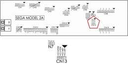
Here’s some pinouts of the PCB cage - you can see the wires there
 

Vamino

Insert coin(s)
vacBacker
Feedback
22 (100%)
Credits
2,632CR
Hello all, long time lurker with no account. New here.

I had a noobie question as I have just acquired a Virtua Fighter 2 dedicated cabinet. This is my first cabinet, however I am a broadcast person by day working in television, so I am comfortable with unusual video cabling/patching configurations, and limited soldering where necessary.

What I want to do is split the video feed. I want the video to keep going to the arcade monitor, but I also want to simultaneously duplicate video signal to go into my OSSC so I can livestream the direct video feed from the cabinet while I'm playing, while keeping the original arcade monitor's feed intact.

I am having a hard time finding a schematic the PCB that is in my arcade machine to find out where the video ports are. Essentially I need to know where the video feed comes out from the board and which cables I need. I did see this thread (https://www.ukvac.com/forum/threads/how-sega-model-2-vga-projector.82640/) which was helpful, but I honestly have no idea what video signal the Model 2 spits out natively (CGA? VGA?) All I know is it is 24Hz. The VF2 cabinet is a US model (family from England but I'm in the colonies now.)

I guess my question is:

1) Where is the video output located on the board?
2) What cable to I need to connect to the board?
3) What splitter cables and other stuff do I need to connect this to my OSSC?

Sound would be nice too, but I'm OK with just getting the video going for now to get my feet wet and then I can fight with sound later.

Sorry for the stupid questions. Any insight much appreciated!
I've done a similar thing to capture this footage from Model 2A stack:


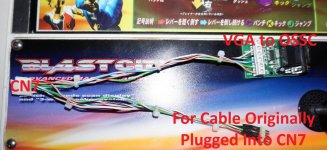
Video from filterboard (cn7) using a home made cable, that cable plugs into Sega 839-0904 sega buffer pcb. One vga output to RT4K/OSSC, other VGA output to Blast city monitor. It needs 12v power though.

In your case you would have to convert VGA back into the 5 pin JST that goes to the display. (Cable that was originally plugged into cn7)

For sound you can make a phono lead that plugs into cn13, and then use a splitter.

I used to do that but I now use a Soundblaster AE-9 and I plug the phono plugs into the the back of the external module to capture sound and then use headphones whilst playing.
 

Skycron

Newbie
Credits
5CR
I've done a similar thing to capture this footage from Model 2A stack:


Video from filterboard (cn7) using a home made cable, that cable plugs into Sega 839-0904 sega buffer pcb. One vga output to RT4K/OSSC, other VGA output to Blast city monitor. It needs 12v power though.

In your case you would have to convert VGA back into the 5 pin JST that goes to the display. (Cable that was originally plugged into cn7)

For sound you can make a phono lead that plugs into cn13, and then use a splitter.

I used to do that but I now use a Soundblaster AE-9 and I plug the phono plugs into the the back of the external module to capture sound and then use headphones whilst playing.
Thanks to everyone for the replies. Everyone has been amazing. John, that confirmation does help quite a bit. It’s good to know this is a standard 60Hz monitor; when I first saw that on a site somewhere, the broadcast part of my brain went, “Uh, 24Hz? Don’t know how that would work, unless it was a horizontal scan rate only, but OK.” And lo, here we are. As silly as it probably sounds, glad my world still makes sense and applies somewhat here. :)

Vamino, that approach sounds right on the money to me, only thing is I don’t really know where Cn7 is on the board. (I did see that video of yours on YouTube and the quality is stunning, btw).

I also don’t really know how to make this video cable or where to start to get 12V power to it, what it would look like or how to power it safely. What does your homemade cable look like? How would I convert VGA back to the display?

If I saw the video cable and how it was put together I could probably splice one up.

On the power side, I won’t lie; doing electrical wiring makes me nervous. Video and audio not so much, but electrical, yes. This is my very first arcade machine, and I do mean my very, very first. I’m somewhat electronically inclined but my knowledge of boards is basically zero. But I can do it if necessary as long as I know what to solder where and with which cabling.
 

Skycron

Newbie
Credits
5CR
Since posting I did some sleuthing and did find a video that showed me where the CN7 connector is, so that I managed to figure out.
(
)

So that just leaves how to make the homebrew cable and do the split (and the VGA conversion back to native signal so the arcade monitor can understand it.)

Eventually, I will replace the onboard monitor with an LCD which theoretically will negate the need to split the VGA or convert it back, as the home brew cable the OSSC will see will just feed the converted signal to the LCD, and can theoretically just split via normal HDMI.
 

Vamino

Insert coin(s)
vacBacker
Feedback
22 (100%)
Credits
2,632CR
You are over complicating things.

You don't need another scaler, you already have OSSC which is a perfect for what you want to do. I've gone through various hardware along my journey and I'm now happy with my setup. But being honest, the equipment I use is overkill and was a bit expensive.

I bought everything over a long period of time and gradually reduced the rats nest of cables/adapters/headphone amps to something much simpler that gives great video quality at low bit-rates, but it came at a cost.

You can do it for a lot cheaper and still have great results.

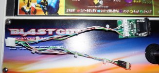
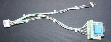
You can get away with something like the following cable which I just made as a proof of concept, but, it may introduce some dimming which can be compensated by turning up contrast/brightness. I need to get some VGA screw terminal blocks to test the cable. (The VGA terminal block connector in the picture is an Ultimarc one which is for sending signals to a monitor, I just attached that to show you what it looks like)

I'll update the thread when I've received the VGA blocks and have tested the cable on my setup.

VGA_Cable.jpg

VGA_Cable.jpg
 
Last edited:

Skycron

Newbie
Credits
5CR
That cable splitter looks perfect to me. What components and wires did you use (so I can source the wires and parts and find them) and what’s the wiring diagram (so I know what cables to put where to build it properly.)

I don’t mind spending more for decent stuff. I’m not worried about the bit rates because it’s all going to go into a broadcast switcher anyway. I deal with the compression at the end of the chain.

Sorry for all the stupid questions. This is all really useful and thanks for helping me out with all this stuff.
 

John Bennett

Senior Member
vacBacker
Feedback
10 (100%)
Credits
5,013CR
Yes, you just T the signaling, no need to convert anything to something and back again for the game monitor.

Also, rule 1.01 of arcade collecting - don't put an LCD monitor into an original, unmodified arcade machine unless you really have to.
 

Skycron

Newbie
Credits
5CR
Is there a diagram so I know what cables go to what? I don’t really understand how they’re going into the T - and how these cables are routed/twisted to go together.
 

Vamino

Insert coin(s)
vacBacker
Feedback
22 (100%)
Credits
2,632CR
Is there a diagram so I know what cables go to what? I don’t really understand how they’re going into the T - and how these cables are routed/twisted to go together.

In your first post you mentioned you work in Television and have a knowledge in cabling, but I'll try to break it down for you in simple terms and provide pictures.

------------------------------------------------------------------------
1/

The pinout for video output from your Virtua Fighter 2 PCB was given to you by John in the first reply. But since you missed that, I'll post a picture from the link he provided.

sega_model2_a_pcb_arcade_filter_board_pinout_CN7.jpg

Your Virtua fighter 2 PCB outputs a 24khz RGBs signal from CN7 on the filterboard using a JST-NH connector:
https://www.jst.com/products/crimp-style-connectors-wire-to-board-type/nh-connector/

RGBs uses 5 wires:
Red, Green, Blue, Sync, Ground.

Make a note of the numbers on the filterboard, and the numbers on the connector.

------------------------------------------------------------------------

2/

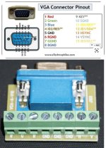
D-Sub 15/VGA can carry RGBs without having to convert anything, so you can easily change the form factor without having to convert anything. Upscalers such as OSSC and Retrotink can process 15khz/24khz/31khz RGBs via their D-Sub15/VGA input.

D-Sub 15/VGA also uses 5 wires to carry RGBs.
Red, Green, Blue, (H) Sync (Pin 13), Ground (pin 10)

VGA Pinout_block.jpg

You can buy VGA terminal blocks from eBay:
https://www.ebay.co.uk/itm/176463478482

------------------------------------------------------------------------

3/

Splitting the signal.

You can either split the RGBs output into 2 outputs using a cable (Cheapest way), or you can use what is known as a buffer board (Correct way).

------------------------------------------------------------------------
4/

Using an unbuffered cable that simply splits the signal.

The following cable is wired using the pinouts explained above. But when it's connected to CN7 on a Model 2 game, it caused my monitor to go dim when also connected to the OSSC/RT4K, and the colours were over saturated when connected to my OSSC/RT4K.

RGBs cable split.jpg

Although the above cable can get the job done, it's not the best solution if you want accurate colours with good image quality. Splitting the cable this way introduces undesirable degradation to the video signal which means you will potentially have to adjust Gamma/Contrast/Brightness levels on your monitor and/or in your video capture software.

When capturing video footage it's best to try and get the cleanest signal possible so minimal changes are required.
------------------------------------------------------------------------

5/

Using a buffer board/Powered VGA splitter.

Buffer boards come in various flavours, some are great but others introduce noise. They are usually powered, so that's something you need to consider if the solution you choose doesn't come with it's own power adapter.

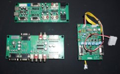
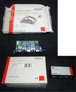
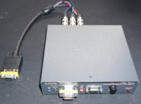
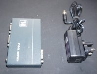
Heres a selection of the buffer boards I've tested and currently have in my box o' bufferboards.

Sega:
Sega_Buffers.jpg

Lindy:
Lindy_Internal_External VGA Splitter.jpg

Extron:
Extron_Buffer.jpg

Kramer:
Kramer_VGA Splitter.jpg
So, you would simply need to get the RGBs signal to the input of the buffer board using JST-NH or D-sub15/VGA depeding on what solution you use.

Then from the buffer board/VGA splitter, one D-Sub15/VGA output would need to go to back to your monitor using the appropriate connectior (JST-NH in your case), and the other D-Sub15/VGA output would go to your OSSC via a standard D-Sub15/VGA cable.

Since your OSSC can accept RGBs signals over D-Sub15/VGA, that's the easiest and cleanest solution.
------------------------------------------------------------------------

6/

Sound output.
Your Virtua fighter 2 PCB outputs (low level, unamplified) sound from CN13 on the filterboard using a JST-NH connector:
https://www.jst.com/products/crimp-style-connectors-wire-to-board-type/nh-connector/

sega_model2_a_pcb_arcade_filter_board_pinout_sound.jpg

Low level sound is easily split using phono adapters.

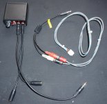
Here's the cable I currently use, and I've also included the amp I used before switching over to the aux input on a Sound Blaster AE-9 external module:

Sound_Amp.jpg

You can use terminal blocks to make life easier:
https://www.ebay.co.uk/itm/165577150070

------------------------------------------------------------------------

And for completion sake, this is what I use to capture high level/amplified sound when using Jamma PCB's which usually have amplified sound direct from the PCB. This line level extractor is intended for use in cars to extract line level output that goes to an amp or subwoofer from the amplified speaker outputs from the head unit.

In this instance, you would cut the video and high level/amplified sound wires after the edge connector on the Jamma loom, you would need to put suitable connectors on the loom to extract sound/video and to also allow reconnection of sound/video back into the loom.

Just as before, video is extracted to a buffer board, so you have 1 output from the buffer board go to the capture solution and 1 output goes back into the Jamma loom to get an image to the arcade cabinets monitor. Just to reiterate, nothing is converted so as long as the cables haven't been swapped around you retain the same original video source.

it's the same with the sound, but the high level/amplified sound from the Jamma loom goes into the low level/line extractor. Then the phono plugs from the low level/line output goes to the capture solution, and the (usually mono) high level/amplified sound goes back into the Jamma loom.

This solution is not required for low level/unamplified sound, it's only for use with high level/amplified sound sources:
Jamma_capture.jpg


------------------------------------------------------------------------
7/
Summary.

So to capture Arcade game footage, all that's required is to extract the video + sound, then use the solutions above to split and then reintegrate sound/video back into the original wiring.

Hopefully the info above is useful, I don't know I could make it any simpler but I'm open to suggestions.

Hope it helps.
 
Last edited:

Skycron

Newbie
Credits
5CR
This is exactly what I needed. Yes I do work in television and am used to cabling - but even we still need pin outs if it’s an unfamiliar board.

This post gives me everything I require. Thanks muchly!
 

Skycron

Newbie
Credits
5CR
Hi all, just a heads up that I was able to splice together a cable and it works great. Have it going to a buffer board and video works great with the OSSC. I haven’t done the audio cable patch through yet but that is next. Thanks again!
 

Skycron

Newbie
Credits
5CR
I want to make some more of these cables but I can’t find any of these 8 pin VGA terminal blocks anymore, and the guy’s eBay link is gone. I’ve searched for these all over but can only find VGA terminal blocks that have way more or way less pins. Anybody know where I can buy more of these 8 pin blocks?
 

Skycron

Newbie
Credits
5CR
Hi John and Vamino, those are readily available where I am, so if I can get those working, it would be cheaper for me by quite an margin. Glomming onto the 8 pin one was essentially my nerves. I honestly was worried I wouldn’t know which terminal to put the stripped cable in with the bigger terminal blocks.

The pinouts on the diagram are very clear, but I was not sure if RGB sync (Pin 4 on the JSN-NH side) would go into 13 or 14 on the VGA terminal block, since I don’t know if “RGB sync” in this case would be Horizontal or Vertical sync as far as I could tell.

I could easily see the RGB and the H V ground on the 8 pin one from Vamino’s picture, so from there I could see exactly where he put the cables in the 8 making it easy to follow it visually.

My thoughts were:
1. I was going to disconnect the original JST cable from CN7 that goes to the monitor.
2) Take one of my newly made 5 pin JSN-VGA terminal cables and run it directly from CN7 into my Extron 160 so the PCB can send the video signal to it
3) Take a VGA Y-cable and connect it to the video output of the Extron, with the first prong of the VGA Y-split going to the OSSC. The second prong would go to the VGA end of my second newly made JSN-VGA terminal cable, feeding the JSN end fed back into the monitor.

There’s a power bar behind the machine so the idea (in theory) is that, when it is turned on, the arcade unit and the Extron machine turn on simultaneously (the Extron is dedicated to the VF2 unit) so that hopefully the Extron’s signal will immediately (or close to immediately) send the video signal to the CRT.

The other thing I thought might work to save time would be to use a 5 pin joystick harness, which would save crimping time by just stripping one end and running the wires to their designated pin out on the VGA terminal. However, I don’t know what kind of wire is being used with the harness below. Bizarrely, I can find very little in terms of NH connectors. Every other type (XH, etc.) I can easily find tons of connectors, crimps etc, wire gauges, etc.

Something like this: https://www.canadianjoysticks.com/joystick-5-pin-to-5-pin-harness/

Let me know if any of that looks incorrect, a bit stupid or not advisable for whatever reason. It’s the first real meddling I’ve done with the machine so despite having opened up many cameras and computers and video equipment the nerves are still there a bit haha.
 
Last edited:

Skycron

Newbie
Credits
5CR
I guess the diet question is: Would “RGB Sync” (CN7 pin 4) go in pin 13 or 14 on the 15 pin VGA terminal block? And can I use that 5 pin harness and chop the ends off to go into the block?
 

Vamino

Insert coin(s)
vacBacker
Feedback
22 (100%)
Credits
2,632CR
I guess the diet question is: Would “RGB Sync” (CN7 pin 4) go in pin 13 or 14 on the 15 pin VGA terminal block? And can I use that 5 pin harness and chop the ends off to go into the block?
Your question is answered in section 2 of the above guide, RGB sync should be pin 13. But you can also confirm what pin it is by using a multimeter continuity test on your block and double checking for yourself.

Not sure why you would cut the original cable, but I guess you could. Personally I'd source the male and female connector and make a bespoke loom rather than hack the og cabling.
 

Skycron

Newbie
Credits
5CR
Thanks. I was mainly going by your VGA pin out diagram. In part 2, the pinouts show Pin 13 on the VGA block as HSync and Pin 14 as Vsync, but Pin 4 on CN7 just says “RGB Sync”. As such I just wanted to double check, though you did mention it in your text which was H/V.

I wasn’t going to hack the original cable that came with it, I was just going to get a few of these (https://www.canadianjoysticks.com/joystick-5-pin-to-5-pin-harness/) and hack those.
 
Last edited:

Vamino

Insert coin(s)
vacBacker
Feedback
22 (100%)
Credits
2,632CR
Thanks. I was mainly going by your VGA pin out diagram. In part 2, the pinouts show Pin 13 on the VGA block as HSync and Pin 14 as Vsync, but Pin 4 on CN7 just says “RGB Sync”. As such I just wanted to double check, though you did mention it in your text.

I wasn’t going to hack the original cable that came with it, I was just going to get a few of these (https://www.canadianjoysticks.com/joystick-5-pin-to-5-pin-harness/) and hack those.
Easiest way to verify is to do a continuity test from the terminal to the pin on the vga connector.

Good call on the cable, should do the job.
 
Top