Nintendo popeye - original or bootleg?

Davespice

Newbie
vacBacker
Credits
72CR
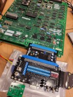
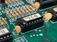
Hi again folks, I was wondering if you can help me identify this board. I think it's an original Nintendo popeye but I'm told the bootlegs were almost identical. I haven't been able to fire it up yet because I don't have the Nintendo to Jamma adapter board (I use a supergun, I don't have a compatible cabinet). So I have go this one on order from Canada.

popeye_top_s.jpg


popeye_bottom_s.jpg


Davespice2023-02-10 13:07:07
 

Davespice

Newbie
vacBacker
Credits
72CR
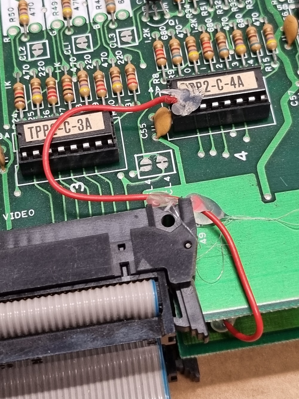
The red wire you can see is an old fix attempt from someone else, apparently the TPP2-C-4A has one broken leg and the red wire is running underneath to the corresponding through hole pin of the socket. I plan to try and either take the 4A ROM image from the MAME set and re-flash a new chip or possibly solder a piece of single core wire onto the broken leg of the original chip, perhaps if I Dremel away a bit of the package to reveal some more metal to get a good solid joint? What advice do you guys have for this?
popeye_fix_attempt1_s.jpg

Davespice2023-02-10 14:06:44
 

Davespice

Newbie
vacBacker
Credits
72CR
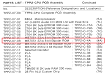
Also I found the type of chip in this PDF (see PDF page 26, printed page number 23). Says it's an MB7051 which I think is a write once prom. Anyone know of an equivalent which is available?
 

cliff_poole

Active member
vacBacker
Feedback
6 (100%)
Credits
1,069CR
The most common equivalent is the 82S123. You may need an older programmer that can handle the bipolar PROMs.

For reference, Google arcade PROM ref which should take you to MikesArcade. I've been going back to that document regularly for many years.
 

Davespice

Newbie
vacBacker
Credits
72CR
Hi folks, my colleague and I have done some work to this board too. Because it's pre-Jamma I ordered this adapter board from pcbjunkie.net in Canada so I could use it with my Supergun. We did a repair the broken leg on TPP2-C-4A, this was accomplished by using a Dremel to remove some of the package to reveal some bare wire to solder onto. We then used a short length of thick wire to make a new leg. It doesn't look pretty but checks out continuity-wise as a fix.

The page for the adapter board says the following;
The original Nintendo pcbs output inverted video signals and require an external sound amplifier, while bootlegs output normal video signals and have an on-board sound amp.
And since this is an original board I set the video jumpers to the inverted position. The video output on a Sony Trinitron KV-25 looked like this:

In the video I first rotate the combined RGB pot on the Supergun, followed by the individual RGB channel pots on the adapter board. So from this I can see the game is running, I can insert coins and start the game, and sort of play it. But the picture is kind of terrible. Can anyone suggest what to do next? Could it be that my TV is not capable of displaying the inverted RGB signal? Or maybe there is still something wrong with the board? Any advice would be appreciated.

Thanks in advance! (y)
 

Attachments

  • 20230324_135721.jpg
    20230324_135721.jpg
    153.4 KB · Views: 9
  • IMG-20230322-WA0005.jpg
    IMG-20230322-WA0005.jpg
    164.1 KB · Views: 8
  • 20230324_135700.jpg
    20230324_135700.jpg
    144.6 KB · Views: 9

Funhouse71

Active member
vacBacker
Feedback
6 (100%)
Credits
1,008CR
You should be getting ar least a picture with that adapter from PCBJunkie but from my personal experience with this particular adapter I never got a sharp picture it was always slightly blurry which seems to be the same with your picture even though it looks like it has sync issues of some sort.

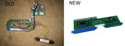
I ended up using one of mikesarcade Nintendo VS unisystem jamma adapters initially bought to use with Super Mario Bros board, it was one of the older jamma adapters he sold shown on the left in the picture below which has 2 seperate edge connectors connected by wires as opposed to his current version which is now incorporated as one board.

NINTENDO VS UNISYSTEM TO JAMMA ADAPTER.PNG

As Popeye and Super Mario used slightly different pinouts I added a female common connector running from the VS jamma board then added to male connectors wired to edge connectors which were wired inividually to cater for the different pinouts for each board, this was so I was able to use one adapter on 2 different boards saving me having to buy another adapter for Popeye.


Mike does sell a seperate Popeye jamma adapter which I expect uses the same components as shown on the bigger VS Unisystem adapter to obtain a crystal clear picture which I can vouch it does provide, so if you do manage to get your sync issues sorted you may want to invest in the mikesrcade adapter at some point.

Popeye Jamma Adapter.PNG
 

Davespice

Newbie
vacBacker
Credits
72CR
Hi Funhouse71, thanks for the input. I am not to worried if I don't get perfect video - I just need to be able to see that the game is running okay and there are no graphics issues. The board will eventually be going back into an original Popeye cabinet at an Arcade in Amsterdam.

I got a useful email from Adrian at pcbjunkie;
Couple of things to look at. First, are you providing -5V power to the adapter / board? The adapter requires -5V for the video conversion, so not having that could impact the image quality.

Since you're in the UK, I'm assuming you're using scart as your RGB input to the TV? Scart is designed for 1Vp-p video I believe (we don't have scart in NA so not 100% sure) while arcade video is 3Vp-p. Do you have some sort of signal attenuator in there?

Just looking at the video once again, and the streaking, I think the video inverter isn't working. For sure look at -5V. Then change the jumpers on the adapter from inverted to normal and see if you get clean video (it will be inverted though). Based on that we can troubleshoot further.
My Supergun is powered by a PC style molex connector (think IDE hard drives) on the left side (see image above) - and this is only connecting +12, +5 and GND from the PSU. But there is a screw terminal for -5V on the Supergun, so I will now do a test where I provide -5V to the Supergun and see if that makes a difference. I also wonder if this could explain why New Zealand Story was not giving any image (see other thread). Bottom line is that it looks like my Supergun is not being 100% compatible with the Jamma standard.
 

Lurch666

Active member
Feedback
21 (100%)
Credits
4,316CR
Peering at the video I think you are going to see graphic errors when you do get this PCB displaying properly.
Not sure but I think the sprites are just moving numbers.
 

Davespice

Newbie
vacBacker
Credits
72CR
Yes possibly, in which case I will try and replace ROM 4A with a brand new chip and flash it with the image from MAME. Perhaps that would explain why that ROM was pulled in the first place which resulted in the leg being broken.
 

cliff_poole

Active member
vacBacker
Feedback
6 (100%)
Credits
1,069CR
When you say JAMMA standard, that really only applies to the pin positions. Sync signals are usually all over the place, especially with bootlegs. Most of us use old monitors with all analogue circuitry which is much more forgiving, just regular tweaks of the geometry controls required. I notice from this and your NZ Story thread you are using a fairly modern CRT TV, could it be having problems locking on to the sync signal ?. The digital control circuitry could be seeing how rough the signal is and blanking the picture to protect the TV.
 

Davespice

Newbie
vacBacker
Credits
72CR
Yes good point, I am soon to be getting an older black Sony Trinitron from early 90s which I believe is fully analogue. A model KV-25X1D.
 

Davespice

Newbie
vacBacker
Credits
72CR
Peering at the video I think you are going to see graphic errors when you do get this PCB displaying properly.
Not sure but I think the sprites are just moving numbers.
Looks like you were right Lurch! (y)

Yesterday I was able to test the board again while supplying -5V via the Supergun as Adrian from pcbjunkie had suggested. That fixed the colour problem and here is the result;

I'm glad the Nintendo to JAMMA board is working. But it looks like we have sprite data corruption. I guess this board doesn't have a post check? This could explain why the 4A ROM was pulled in the first place which resulted in a leg becoming broken off.

I would appreciate some guidance on which ROM the sprite data is stored in, are there tools to look at this? Instinct says the 4A ROM because it was pulled in the past but that could also be a red herring. I could dump all the ROMs and compare them with the MAME set too I suppose?

Also any advice on what device I can use to flash a write-once PROM like the MB7051 (as per the manual) which is apparently equivalent to the 82S123? I have available a GQ-4x4 and a TL866. Thanks!
1680850563644.png
 

cliff_poole

Active member
vacBacker
Feedback
6 (100%)
Credits
1,069CR
There are lots of different ways to figure out which graphics are in which ROM. The quick and dirty way is to briefly short together a couple of data lines while watching what happens on the screen. Other ways include, video probe, pulse injector, or just plain running with the ROMs removed.

From your video, it looks like the tile data in the ROMs is OK, just being displayed in the wrong order. Check the ROM select lines and addressing circuitry.
 
Top