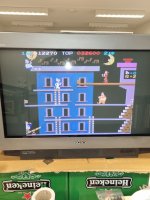
Nintendo popeye - original or bootleg?

Davespice

Newbie
vacBacker
Credits
72CR
From your video, it looks like the tile data in the ROMs is OK, just being displayed in the wrong order. Check the ROM select lines and addressing circuitry.
In the popeye service manual some of the parts are listed as data selectors, are these what you mean?
74LS151 - 8 to 1 Line Data Selector (1 of)
74LS157 - Quad 2 to 1 Line Data Selector (13 of)
7 4LS257 - Quad Data Selector (2 of)
 

olin

Newbie
Credits
41CR
Looking at the mame source driver. The 4A is background palette. 5n is 'gfx1' (mame has a comment that says 'first half is empty') , 1e, 1f, 1j and 1k are 'gfx2'. They seem to be socketed, so probably the first step is to verify the gfx 1 and 2 contents.
 

Lurch666

Active member
Feedback
21 (100%)
Credits
4,280CR
AS olin says check the roms at 1e,1f,1j and 1k because if I'm following it right the schematics show they are obj (object) roms which suggests to me sprites.
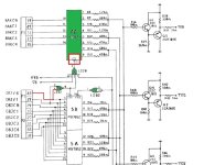
If they are OK then go on to check the three 74LS174s at 1L,2L and 3L that provide the address signals for those roms and If you follow the schematics (video sheet 2 of 3) you can see the output of those roms goes into various LS377,LS194 and LS157 chips which need to be checked next.
 

olin

Newbie
Credits
41CR
Considering the age of the board and the fact that the program roms seem OK, it might be better not to pull the GFX roms (as I suggested earlier) because you may either damage the ROM pins or the reseated pins will not make a good contact in the oxidised socket. Checking the signals as Lurch666 suggested, seems to be safer approach.
 

Lurch666

Active member
Feedback
21 (100%)
Credits
4,280CR
Obviously the choice is yours but I would pull and test the sprite roms first.
If they are in such a bad condition that they fall apart when removed then they need replacing anyway and if the sockets are oxidised or just old and worn out they will need to be replaced as well.
 

sukhbir

Active member
Feedback
46 (100%)
Credits
1,634CR
looks like an addressing issue with the object roms ,you can do a selftest first to rule out the roms.On the cpu board locate connector (P8) and short pin 1+2 then power on the board.You should now be in the test mode.

if roms and rams are ok then it’s time to get hold of schematics and look at the data and address buses from the object roms which are located at 1k,1j,1f,1e.

good luck (y)
 

Davespice

Newbie
vacBacker
Credits
72CR
Hi folks, I am still working on this Popeye board. I found that engaging the self-test mode confirmed the ROM checks all pass. So it's looking more like there is a problem with the addressing/switching circuitry. A colleague of mine is helping me, he ran the board on an oscilloscope and found that the ground circuit had a lot of noise on it. An inspection of the crystal frequencies revealed they didn't look at all clean. We then looked closely at the capacitors and found that several, which are the old type with the rubber bung, looked a bit swollen and the bung was starting to come out on some of them. So we are going to recap everything and replace the crystals. That may or may not fix it though, but it at least means not having to worry about leaks for 30+ years.

Perhaps a combination of the aging crystals and caps is causing the noise on the ground circuit which could also be responsible for a latched trace? We'll know once we power it back up again.

Question for you all... one of the crystal types we are having difficulty finding. Can anyone help?
20 .160 MHz Crystal (TPP2-06-33)

It's the one at D8 on this image;
popeye_bottom_s.jpg
 

Davespice

Newbie
vacBacker
Credits
72CR
Hi folks

So it's been a while since I wrote an update on this board, work has been done on it occasionally over the last few months and we have managed to solve the corrupted sprites issue however we now have a problem with the video output, possibly caused by something we did.

Here's a list of what has been done;
  • All capacitors replaced - no effect
  • All ROMs dumped and cross checked against images from MAME (all were fine)
  • All 74LS151, 74LS157, 74LS257 removed tested and replaced socketed - no effect
  • TC5501P x 3 RAM replaced
    • Note: this fixed the corrupted sprites, after this we could see that Popeye, Olive-oil and Bluto looked normal again
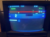
However now we are facing a video corruption issue which looks to me like a problem with the signal itself, you can see bands of colour on screen stretching between two objects of the same colour - such as the hearts Olive oil is throwing.

I am not exactly sure at which stage the video issue started, a colleague is working on the board at his home. He says it always looked like this since he started working on it. We have tested the screen, SCART cable and supergun set up with a 60 in 1 board to check it's fine and it is.


Any ideas would be welcome. Thanks again! (y)
 

sukhbir

Active member
Feedback
46 (100%)
Credits
1,634CR
Hi folks

So it's been a while since I wrote an update on this board, work has been done on it occasionally over the last few months and we have managed to solve the corrupted sprites issue however we now have a problem with the video output, possibly caused by something we did.

Here's a list of what has been done;
  • All capacitors replaced - no effect
  • All ROMs dumped and cross checked against images from MAME (all were fine)
  • All 74LS151, 74LS157, 74LS257 removed tested and replaced socketed - no effect
  • TC5501P x 3 RAM replaced
    • Note: this fixed the corrupted sprites, after this we could see that Popeye, Olive-oil and Bluto looked normal again
However now we are facing a video corruption issue which looks to me like a problem with the signal itself, you can see bands of colour on screen stretching between two objects of the same colour - such as the hearts Olive oil is throwing.

I am not exactly sure at which stage the video issue started, a colleague is working on the board at his home. He says it always looked like this since he started working on it. We have tested the screen, SCART cable and supergun set up with a 60 in 1 board to check it's fine and it is.


Any ideas would be welcome. Thanks again! (y)

 

Funhouse71

Active member
vacBacker
Feedback
6 (100%)
Credits
1,008CR
I have a fully working Nintendo Popeye I worked on and got back up and running so if you need me to take any logic readings for certain chips you want to rule out as suspect I am happy to help.
 

Davespice

Newbie
vacBacker
Credits
72CR
Hi folks, so a bit of necromancy here. I thought I would write an update to close the loop on this popeye board in case anyone else gets the same issue in the future. We finally fixed it. The issue was a continuity break in the region of the U8 chip on the GFX board. This also forced me to get better with using an oscilloscope - so I have come out of this having learnt a lot. I have to also thank Funhouse71 who corresponded with me a lot over email during the past few months.

Expalantion;
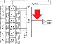
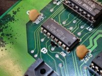
Despite the bad colours we could see that the background was not being drawn at all, and it was the same without the 4A chip inserted or removed. We also had a new 4A chip made to replace the original one with a broken leg (in case our repair to the leg had caused internal damage). This led us to suspect there might be a problem with the chip select input to 4A and so we scoped out the signals going into it. This confirmed chip select was never happening. So we also removed, tested and socketed the 5D and 5E chips to eliminate those (they were both fine). So therefore we went one step back and scoped the inputs to 5D and 5E and this revealed that pin 6 of 5E was always hovering at about 1.8V. The signal for this pin goes to the 5J chip on the GFX board via pin 43 of the P1 edge connector. So we turned our attention to the GFX board and found there was no continuity between 5J pin 4 and pin 43 of P1 - so therefore there must be a continuity break somewhere on the GFX board. Next we followed the trace from 5J pin 4 all the way across the board and found a tiny nick just beside U8. It looks like perhaps someone in the past had been probing there and they slipped off the leg of the chip and damaged the trace just below it. To test if this was the issue we just added an enamel wire to the bottom side of the board going between a via on the other side of U8 over to the through hole solder joint of pin 43 on P1. That was it! Normal graphics restored.

Thanks again to everyone who replied to this thread, to Funhouse71 and to my colleagues Neil Beadle and Paul Honig who helped me with the work.
 

Attachments

  • popeye_debug_1 tpp2 cpu schematic sheet 3.jpg
    popeye_debug_1 tpp2 cpu schematic sheet 3.jpg
    108.1 KB · Views: 7
  • popeye_debug_2 tpp2 video schematic sheet 2.jpg
    popeye_debug_2 tpp2 video schematic sheet 2.jpg
    86.2 KB · Views: 8
  • popeye U8.jpg
    popeye U8.jpg
    157.7 KB · Views: 8
  • popeye U8 microscope shot.jpg
    popeye U8 microscope shot.jpg
    160.9 KB · Views: 9
  • 20240730_171011.jpg
    20240730_171011.jpg
    80.7 KB · Views: 8

Funhouse71

Active member
vacBacker
Feedback
6 (100%)
Credits
1,008CR
Hi folks, so a bit of necromancy here. I thought I would write an update to close the loop on this popeye board in case anyone else gets the same issue in the future. We finally fixed it. The issue was a continuity break in the region of the U8 chip on the GFX board. This also forced me to get better with using an oscilloscope - so I have come out of this having learnt a lot. I have to also thank Funhouse71 who corresponded with me a lot over email during the past few months.

Expalantion;
Despite the bad colours we could see that the background was not being drawn at all, and it was the same without the 4A chip inserted or removed. We also had a new 4A chip made to replace the original one with a broken leg (in case our repair to the leg had caused internal damage). This led us to suspect there might be a problem with the chip select input to 4A and so we scoped out the signals going into it. This confirmed chip select was never happening. So we also removed, tested and socketed the 5D and 5E chips to eliminate those (they were both fine). So therefore we went one step back and scoped the inputs to 5D and 5E and this revealed that pin 6 of 5E was always hovering at about 1.8V. The signal for this pin goes to the 5J chip on the GFX board via pin 43 of the P1 edge connector. So we turned our attention to the GFX board and found there was no continuity between 5J pin 4 and pin 43 of P1 - so therefore there must be a continuity break somewhere on the GFX board. Next we followed the trace from 5J pin 4 all the way across the board and found a tiny nick just beside U8. It looks like perhaps someone in the past had been probing there and they slipped off the leg of the chip and damaged the trace just below it. To test if this was the issue we just added an enamel wire to the bottom side of the board going between a via on the other side of U8 over to the through hole solder joint of pin 43 on P1. That was it! Normal graphics restored.

Thanks again to everyone who replied to this thread, to Funhouse71 and to my colleagues Neil Beadle and Paul Honig who helped me with the work.
Glad to see it fixed finally after a long haul!...also flagged up an issue with my board along the way which I finally fixed ;)
 
Top