Arm Champs 2 power confusion

Davespice

Newbie
vacBacker
Credits
72CR
Hi folks

So I'm working on a Jaleco Arm Champs 2 - it is in semi poor condition. Internally there is metalic corrosion on the upward facing surfaces - as if the machine was exposed to some corrosive dust like plaster dust in the past. So for example the top surfaces of the PSU cages are corroded but the sides are all totally fine.

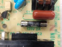
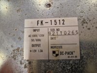
The machine has a UK plug on the mains lead but the internal PSUs look like US mains ones still - I took them apart to check/clean and found they had 125V 2A fuses in both of them. I attach a few pictures of the smaller one. I tried to power it up using 230V mains (before I realised the input voltage) and of course the fuse went bang. Does anyone know if these are slow or fast blow? I have a 1500W step down transformer for US mains to try it with but need to replace the fuse now.

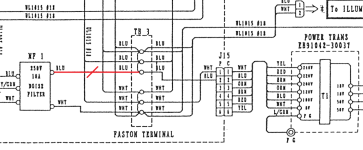
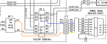
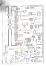
I am looking at the schematic and mains voltage is going to various places from the Faston Terminal at the bottom (C8) - especially it goes to the Motor Control board in the middle (C5/6) which is labelled as 100V (see TB1 pins 1 and 2). So I am thinking that it probably is not good to supply 230V mains power to that board right - as I would imagine that power is being switched to the motors.

I am wondering if the UK plug is just a red herring, does anyone know if these machines can be run on 230V but with the two PSU units replaced? Or would that cause damage to the motors if run on that voltage?

Thanks in advance
Dave

P.S. Any advice on renovating these things would be gladly received.
 

Attachments

  • PSU fuse.jpg
    PSU fuse.jpg
    110.6 KB · Views: 23
  • PSU model.jpg
    PSU model.jpg
    140.4 KB · Views: 24
  • PSU wires.jpg
    PSU wires.jpg
    53.6 KB · Views: 25
  • Arm Champs schem COLOUR.png
    Arm Champs schem COLOUR.png
    308.3 KB · Views: 27
Last edited:

69er

Active member
Feedback
6 (100%)
Credits
1,546CR
It may have had some ‘rogue’ upgrades by owners during its 40 year life? That fuse has certainly seen more power than it expected!!!!

The wiring diagram does show a two pin supply to the monitor so I would suggest that’s a 100v chassis not normally earthed

Also shows two pin input to power supply , tho it is earthed also ? On the diagram which I can’t quite enlarge enough to see detail

You need to follow the mains wire inside and it would ‘likely’ go directly to a step down transformer as implied by the 100/120v input label / badge along with 12 v which will probably be the motor voltage? Maybe fed by the switch mode psu pictured with a screw missing ,

I have worked on a couple of these in the past but don’t recall the inner wiring as they were both if I recall monitor faults? Long time ago!

It’s very possible connecting mains 240v direct is not the correct supply?

Look around inside for positions where a step down may have been sited and maybe removed , confusing future users?

A tip for checking motors is take them off wiring loom and link them up to a car battery either way round as they are likely 12v dc and work in both directions switched by the control pcb ? Try them plus /minus and minus/ plus they should turn both ways ?

Take out the psu unit repair the fuses (probably quick blow) and supply it with approx 100 v ac see if it works on bench to deliver 12v dc at the output !

100/120vac step down Xformers are quite easy to find wire one to a mains lead and connect the output side 100v to the small switch mode psu you have pictured … study it more see if it indicates 100v input too? If the fuses still blow then it’s quite likely the bridge rectifier is shorted somewhere? Or there may be a zener diode also shorted on its output?

You might be as well fitting a replacement 12v dc/ from 100 v input as more internal components could be damaged by wrong input voltage? Even tho the fuse may have done its job?

The blue line on the diagram also supplies the fan which if examined should also show if it’s label 100v ac or mains ?

Best I can suggest ! Also clean it better with an air line perhaps ?
 
Last edited:

ExZX

Active member
Feedback
24 (100%)
Credits
1,238CR
That PSU isn't a switching one. It's US voltage only
There are a couple of people on the Facebook group who own these cabs so you're probably best asking them for pics of the internals and any info they have. I've done an image search and can't find anything decent as it's a rare cab.
Also on the schematics from what I can work out it might use x2 PSUs? Am unsure as it's a low quality image.

armchamps2-01.jpgarmchamps2-02.jpg
 

Davespice

Newbie
vacBacker
Credits
72CR
It may have had some ‘rogue’ upgrades by owners during its 40 year life? That fuse has certainly seen more power than it expected!!!!

The wiring diagram does show a two pin supply to the monitor so I would suggest that’s a 100v chassis not normally earthed

Also shows two pin input to power supply , tho it is earthed also ? On the diagram which I can’t quite enlarge enough to see detail
Thanks for looking into it, the original file is about 3500x4900 pixels so if you download it locally you should be able to zoom in a bit.
You need to follow the mains wire inside and it would ‘likely’ go directly to a step down transformer as implied by the 100/120v input label / badge along with 12 v which will probably be the motor voltage? Maybe fed by the switch mode psu pictured with a screw missing ,
I've got a couple of stand alone transformers that I can use for this. I feel like the motor voltage could be 18V or 50V (see output rails for the transformer).
I have worked on a couple of these in the past but don’t recall the inner wiring as they were both if I recall monitor faults? Long time ago!

It’s very possible connecting mains 240v direct is not the correct supply?
This is what I am thinking too - based on the fuse values in the two main PSUs.
Look around inside for positions where a step down may have been sited and maybe removed , confusing future users?
Next time I am working on it I will look around inside it for this.
A tip for checking motors is take them off wiring loom and link them up to a car battery either way round as they are likely 12v dc and work in both directions switched by the control pcb ? Try them plus /minus and minus/ plus they should turn both ways ?

Take out the psu unit repair the fuses (probably quick blow) and supply it with approx 100 v ac see if it works on bench to deliver 12v dc at the output !
Yeah - that was what I was doing when I blew the first fuse, I just had not clocked it was expecting US mains at that point.
100/120vac step down Xformers are quite easy to find wire one to a mains lead and connect the output side 100v to the small switch mode psu you have pictured … study it more see if it indicates 100v input too? If the fuses still blow then it’s quite likely the bridge rectifier is shorted somewhere? Or there may be a zener diode also shorted on its output?

You might be as well fitting a replacement 12v dc/ from 100 v input as more internal components could be damaged by wrong input voltage? Even tho the fuse may have done its job?
I think I will replace the fuse with a new one, and power it via US mains to see what happens. If I measure +12V and -12V on the other terminals it is probably still okay to use it.
The blue line on the diagram also supplies the fan which if examined should also show if it’s label 100v ac or mains ?

Best I can suggest ! Also clean it better with an air line perhaps ?
Thanks I will look into the fan as well. The plug on the mains lead just really threw me :)
 

Davespice

Newbie
vacBacker
Credits
72CR
That PSU isn't a switching one. It's US voltage only
There are a couple of people on the Facebook group who own these cabs so you're probably best asking them for pics of the internals and any info they have. I've done an image search and can't find anything decent as it's a rare cab.
Also on the schematics from what I can work out it might use x2 PSUs? Am unsure as it's a low quality image.
Yeah interestingly my machine doesn't have the cages protecting the game PCB (left side), the motor controller PCB (bottom) or the power chain (back). I wonder if they were robbed away at some point - but thanks for sending these images. Yes it does have two PSUs - I guess because of the required current?
 

bones

Active member
Feedback
15 (100%)
Credits
1,626CR
Don't take this for Gospel as the schematics are difficult at best. But I'm seeing the clutch (top) with 18vdc supplied to it from the motor controller and the dc motor being supplied 50vdc from the motor controller. Trying to figure out the 100v ac, does this have fluorescent tubes too ?
 

bones

Active member
Feedback
15 (100%)
Credits
1,626CR
Ok scrap that ,the 18v ac is the input to the motor control unit marked 'p' in ,it doesn't specify a voltage for the output 'p' out but it is going to the clutch. Same with the 50v ac, it is marked as 'm' in at the motor control unit but again the 'm' out doesn't specify a voltage but goes to the dc motor.
 

bones

Active member
Feedback
15 (100%)
Credits
1,626CR
I can see that the motor is protected by a 5 amp fuse on the switch plate.
The mains input goes through 2 door switches as well as an 8 amp fuse on the switch plate too and then off to a mains filter, the out wires from this are shown as blue and white and the blue goes to the 100v winding on the transformer and the white to the 0v winding and this is where the above 2 voltages 50v ac and 18v ac come from and go off to the motor control unit. I can see the mains filter is rated at 250v 10 amp and that the transformer has windings for 240,220,200,120 and 100v. So I must assume provision was made for it to run on 240v with some small changes. IE changing the switch mode psu's input choice to 240v and using the 240v primary winding(yellow) instead of the blue one at the transformer. Nice machine btw
 

bones

Active member
Feedback
15 (100%)
Credits
1,626CR
So you may well have a 100v machine, if you have and you have connected 240v then both switch mode psu's would have blown fuses minimum but I'd check any fuse you can find. NB the psu you show outputs 12vdc only. The second psu indicated on the drawing supplies both a 12vdc and a 5vdc(logic) and both psu's are shown with the ac input wires being blue and white indicating a 100v ac supply. So think you're going to need to get your meter out and do some investigation. Normally you'd expect the motor to have a plate on it with its details possibly the clutch too. Found it strange that the motor cables are referred to with a 'm' and the clutch as a 'p' but elsewhere on this schematic there is a 'pulse' mentioned which may relate to how they use the clutch for the game and hence referencing its cables with a 'p'. Crikey would love to be working on this,proper good fun cabinet.
 

bones

Active member
Feedback
15 (100%)
Credits
1,626CR
Right anyways, if the 8 amp fuse has not blown then I can see no other protection for the motor control unit. I would say that I would think that the clutch and the motor should be ok as a combination of logic and power devices will control the outputs to them. I guess a picture of the guts of the motor control unit component and pcb side would help determine what it does and hopefully this has some fuses across the inputs. As I think 69er touched on,as the motor is dc voltage then at the very least there would be a bridge rectifier to convert the ac to dc and this hopefully is rated much lower than 240v, but really need to see the unit in detail tbh. Fingers crossed for you at this point.
 

Davespice

Newbie
vacBacker
Credits
72CR
So I never actually powered up using the mains lead attached to the machine. I removed the whole power unit from the machine - which includes both PSUs, the Faston Terminal and transformer. Was heavy as hell. I then took apart both PSUs to check them internally for any signs of corrosion or leaking capacitors. I powered up the smaller of the two using a short EU mains lead with spade connectors on the ends (visible in the PSU wires image I attached to the original post at the top). My plan was to power it up and measure if I was getting 12V - but of course, at that point I had not clocked the input voltage (even though I had taken a photo of it).

So the fuse in the other, larger, PSU is still okay and I will plan to test this with a step down transformer that I have on hand. I reckon the fuse did it's job and saved the smaller PSU and probably if I just swap out the fuse everything will be good. I will probably try to run the machine at US voltage to restore it to working order and only then think about conversion to EU voltage.

It seems like it would be straightforward to do if I replaced both power supplies and rewired the input to the transformer (so blue goes to red). However the only thing I would worry about is the 100V pins on the Motor Control unit TB1 at ~location C6. If 220VAC went in there the magic smoke would probably escape I think.

I did not see any florescent tubes in it but there is a mod just behind the monitor where two LED light bulbs have been installed.
 

bones

Active member
Feedback
15 (100%)
Credits
1,626CR
Great video !!! We had a basic version with no monitor when I was managing a small arcade here many moons ago. I got called to it one day "I think it's gone faulty"they said. I got there and there was a big chap there called Cliff with his hands firmly grasping the hand/arm and the machine was tilted at a 45° angle lol. Turned out it had gone faulty and the power was maximum all the time, much respect for Cliffs strength was given.
 

bones

Active member
Feedback
15 (100%)
Credits
1,626CR
In regards to going forward I think your approach is the right way. I'd stick at 100v ac to avoid any messing around. Intrigued to know why it needs a 12vdc at 1 amp and a 12vdc at 2amp supplied by separate PSUs. 12vdc is normally just coin mech,meters,button bulbs and possibly sound.
I'd be tempted to power it up in stages ie maybe have the voltages going to the motor control unit disconnected just so you can be sure the transformer is working and giving the correct outputs for example. You know prove each section is correct in that respect before you fully turn it on so to speak. I would imagine a step down transformer would do the job as the 100v input does go through the mains/noise filter before going off anywhere else. If there is a proper boxed unit I might be tempted to get one once you've proved it's all working. Only other thing is if you do have to get a new switch mode psu or 2 remember to get one that can be changed down to I think it's 115vac but 100vac will run that fine. Don't buy the cheap Chinese dong ones though,they certainly don't have the short circuit protection they boast of, watched one fry and belch smoke in a Daytona USA that had the coin mech 12v wire shorted to ground by the coin door. A suzohapp version will serve you well. Anyway looking forward to the hopefully positive updates on this.
 

69er

Active member
Feedback
6 (100%)
Credits
1,546CR
Thanks @ExZX
Yes that’s in the “Dunes” annexed to THE SANDY BAY INN in sandbank rd looks like Dave Appleyard has had someone convert it to lcd ? Tho it was always a tall narrow display ?

Some time ago I worked in there on a regular basis maybe once or twice a week doing his daily attentions etc ..

I converted the coin mech to new 50p about 25 years ago and since did a monitor issue (if I recall… big resistor near lopt dry joint overheating loss of pic) on a intervideo crt and it had that picture glitch then so would assume it’s on the logic pcb? Only occurs in play… Or poor connect wiring somewhere not found. The game as a whole pretty reliable otherwise but tucked away in a corner at the time as space in there is tight.

I fell out with him almost 10 years ago and stoppped going there . His favourite thing was “ great job what do I owe you? “ I would reply an amount he always paid ok, but on giving me the cash he often said “ Oh! And just while you’re here can you top up the 2p changer ,” involving emptying pusher trays for up to an hour or “forgot to mention that Roll a coin belt keeps stopping “ knowing the belt bearings were gone in the back…he would only be there briefly to check bar and arcade takings and then just disappear after ordering any beer supplies and briefing me on notes made by his kiosk operator for none pay outs etc….

. A two hour strip down and acquire new roller shaft and bearings a week or so out of order… spent £166 on parts and when I went a week later the scrap man had took it and he never paid up. So never did his arcade again but we supplied his cabaret bar pub side with two Cat C £100 fruits so had to go in now and then but usually dodged it and sent Daniel in as fruits was his department. When he rang a time or two I lied saying I was out of the area or even told him I invested in a pub refurb to stop him mithering

To be fair he often wasn’t there and all the keys were tagged in a couple of box trays in his office behind the bar .. in later years it meant I just had to sneak in and out of the Moreton Arms across the road as we did an empty there most weeks in summer and fruits often ran low on pounds or note jams as they were heavily used - they also had a mini arcade kids room in the back.

He is a pain and closes early every year boarding up windows as soon as August bank holiday weekend is over.. he refused to pay staff on bar if it wasn’t packed out .

On a plus side he did book some top acts off tv talent shows and while parents enjoyed them the kids wandered down into the arcade ….. “ mum … I need another pound for 2ps “ captive audience !!!

The other one I worked on was at Pensarn Pleasure Beach Abergele, but it got chucked out following a few repeat breakdowns and low income. Many years ago. Both plugged in to regular wall socket supply 240v

(200-215 v usually in that area due to high density of arcades and caravan parks drawing the supply down especially tea times Maygay fruits often landed between symbols leading to claims so needed be tapped down to 220 input else the Mars accept also was poor if 12v dropped at the coin mech)
 
Last edited:

bones

Active member
Feedback
15 (100%)
Credits
1,626CR
Oops just noticed that the 12vdc say 1 amp on both PSUs and the grounds are linked together, looks like the 5vdc is rated at only 1 amp too but could be my eyes lol
 

Davespice

Newbie
vacBacker
Credits
72CR
Folks - I just realised something really important. The schematic has a mistake on it which was really confusing to me. See attached images below - there is a line coming from the noise filter to the Faston Terminal which is wrong (shown in red). This is not connected on my machine and what I found was that there is an orange wire going from the noise filter to the J15 terminal yellow wire (for 240V input). This is explains the UK plug socket on the mains wire.

Moreover - the blue and white wires are actually OUTPUTS of the main transformer and they feed back to the Faston Terminal, which will be at 100VAC and this is then distributed to other parts of the cabinet. I have tested this today (powering via EU mains voltage) and measured 100VAC across the blue and white sides of the Faston Terminal. I should have studied the manual more closely, pages which explain this are attached.

Massive face palm moment :ROFLMAO:
 

Attachments

  • wrong.png
    wrong.png
    228.1 KB · Views: 12
  • right.png
    right.png
    222.8 KB · Views: 14
  • 1000003707.jpg
    1000003707.jpg
    58.1 KB · Views: 14
  • 1000003704.jpg
    1000003704.jpg
    63.2 KB · Views: 16
Top