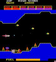
I am playing custodian to Rav's Amidar cab at present which has had a bit of a weird control panel issue.
For those not familiar, the control panel has 2 buttons and a joystick, the 2 buttons also act as player 1 and player 2 start as well as being tied together as jump.
When it arrived (pretty much straight off the back of Revival), the player 1 start button would not function but the jump function would on that button, the player 2 start button would work but the jump on that side would not.
On inspection under the panel there appears to be diodes in place on the switches.
The ground wire goes around the standard points on the leaf switches, there is a blue/white which is for jump and then a brown/white for player 1 start with a diode across the blue/white -> brown/white.
The setup is duplicated on the player 2 start with blue/white for jump and black/white for p2 start.
The lower leaf connector on p2 has the black/white and the upper with the blue/white, the diode banded (+) end is at the black/white pin.
What I found was that upon arrival the p1 side had blue/white on the bottom part of the connector and brown/white on the upper.
I have reversed the connections so that blue/white is on upper on both and the alternate is on the bottom, the diode on p1 has been replaced, these seem to be germanium type similar to those found in Zaccaria Invaders and probably a few other games.
However, what i've got now is weird.
P1 start works
P2 start works
Jump is now a bit intermittent - takes a few presses to work.
If I hook that board up to a JAMMA rig it works perfectly so my guess is the problem has to be in the control panel wiring.
I've traded the wires back to the edge connector and they all land at the correct pins.
Amidar, in upright mode uses P1 controls for both P1 or P2 unless P2 controls are present so there's only one set of wires hitting the PCB edge.
As the IC's are expecting separate inputs what are the diodes for?
What would be the effect of just removing the diodes and having the panel send signals to the p1/jump, p2/jump on each press?
P1 is wired separate to P2 so pressing P1+JUMP at the same time shouldn't cause confusion right?
RGP2013-12-19 10:50:04
For those not familiar, the control panel has 2 buttons and a joystick, the 2 buttons also act as player 1 and player 2 start as well as being tied together as jump.
When it arrived (pretty much straight off the back of Revival), the player 1 start button would not function but the jump function would on that button, the player 2 start button would work but the jump on that side would not.
On inspection under the panel there appears to be diodes in place on the switches.
The ground wire goes around the standard points on the leaf switches, there is a blue/white which is for jump and then a brown/white for player 1 start with a diode across the blue/white -> brown/white.
The setup is duplicated on the player 2 start with blue/white for jump and black/white for p2 start.
The lower leaf connector on p2 has the black/white and the upper with the blue/white, the diode banded (+) end is at the black/white pin.
What I found was that upon arrival the p1 side had blue/white on the bottom part of the connector and brown/white on the upper.
I have reversed the connections so that blue/white is on upper on both and the alternate is on the bottom, the diode on p1 has been replaced, these seem to be germanium type similar to those found in Zaccaria Invaders and probably a few other games.
However, what i've got now is weird.
P1 start works
P2 start works
Jump is now a bit intermittent - takes a few presses to work.
If I hook that board up to a JAMMA rig it works perfectly so my guess is the problem has to be in the control panel wiring.
I've traded the wires back to the edge connector and they all land at the correct pins.
Amidar, in upright mode uses P1 controls for both P1 or P2 unless P2 controls are present so there's only one set of wires hitting the PCB edge.
As the IC's are expecting separate inputs what are the diodes for?
What would be the effect of just removing the diodes and having the panel send signals to the p1/jump, p2/jump on each press?
P1 is wired separate to P2 so pressing P1+JUMP at the same time shouldn't cause confusion right?
RGP2013-12-19 10:50:04

 However, jump should work