3 days ago I started again the sports malice ") to fix a great game from the 80's AMIDAR. To begin with, I started with the eproms, they were gone most likely because they are more than 40 years old. I had trouble programming them because my programmer didn't support 25v, so I had to buy one. So the first picture after programming the roms was a very cool carpet
to fix a great game from the 80's AMIDAR. To begin with, I started with the eproms, they were gone most likely because they are more than 40 years old. I had trouble programming them because my programmer didn't support 25v, so I had to buy one. So the first picture after programming the roms was a very cool carpet
After investigation and replacement of 3 chips 6P, 6K and 6J the result slightly changed :
I found two more half blown 74LS367 chips. After their replacement, the situation improved a little more:
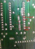
After checking the entire address bus and data bus I found something strange that I couldn't find information about anywhere. After checking the address bus A11 is connected to ground with a jumper, as the jumper gives the option of choosing whether A11 is connected to ground or to pin 5 of 2A ?????

when is a11 connect to ground (that's how it is from the factory):

i need help about this .
to fix a great game from the 80's AMIDAR. To begin with, I started with the eproms, they were gone most likely because they are more than 40 years old. I had trouble programming them because my programmer didn't support 25v, so I had to buy one. So the first picture after programming the roms was a very cool carpet when is a11 connect to ground (that's how it is from the factory):
i need help about this .
Attachments
Last edited:

