[Edited to correct +12V to be -5V at U, and +5V on V, W & X - all corrections will be applied here - Judder]
Thanks guys for the replies
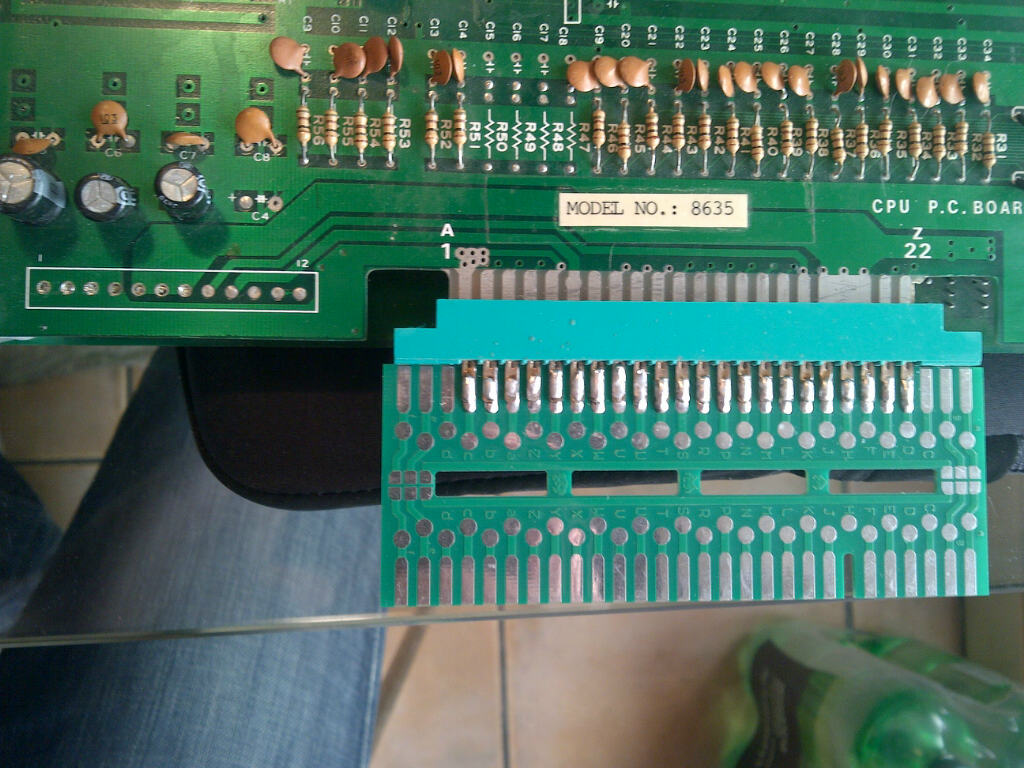
So I took the 44 pin original pinout, and added in my power connections which were using empty pins on the original wiring and ended up with the following:
[font="Courier New, Courier, mono"] ________________________________________________[/font]
[font="Courier New, Courier, mono"] |Component Side | |Solder Side |[/font]
[font="Courier New, Courier, mono"] |---------------|-------|-------|--------------|[/font]
[font="Courier New, Courier, mono"] |Ground | 1 | A |Ground |[/font]
[font="Courier New, Courier, mono"] |---------------|-------|-------|--------------|[/font]
[font="Courier New, Courier, mono"] |Video Red | 2 | B |Video Ground |[/font]
[font="Courier New, Courier, mono"] |---------------|-------|-------|--------------|[/font]
[font="Courier New, Courier, mono"] |Video Green | 3 | C |Video Blue |[/font]
[font="Courier New, Courier, mono"] |---------------|-------|-------|--------------|[/font]
[font="Courier New, Courier, mono"] |Video Sync | 4 | D |N/U |[/font]
[font="Courier New, Courier, mono"] |---------------|-------|-------|--------------|[/font]
[font="Courier New, Courier, mono"] |Speaker + | 5 | E |Speaker - |[/font]
[font="Courier New, Courier, mono"] |---------------|-------|-------|--------------|[/font]
[font="Courier New, Courier, mono"] |+12v | 6 | F |<Key> |[/font]
[font="Courier New, Courier, mono"] |---------------|-------|-------|--------------|[/font]
[font="Courier New, Courier, mono"] |N/U | 7 | H |N/U |[/font]
[font="Courier New, Courier, mono"] |---------------|-------|-------|--------------|[/font]
[font="Courier New, Courier, mono"] |Coin Sw | 8 | J |? |[/font]
[font="Courier New, Courier, mono"] |---------------|-------|-------|--------------|[/font]
[font="Courier New, Courier, mono"] |Coin Meter | 9 | K |? |[/font]
[font="Courier New, Courier, mono"] |---------------|-------|-------|--------------|[/font]
[font="Courier New, Courier, mono"] |? | 10 | L |? |[/font]
[font="Courier New, Courier, mono"] |---------------|-------|-------|--------------|[/font]
[font="Courier New, Courier, mono"] |Service Sw | 11 | M |Slam Sw |[/font]
[font="Courier New, Courier, mono"] |---------------|-------|-------|--------------|[/font]
[font="Courier New, Courier, mono"] |1P sw | 12 | N |2P sw |[/font]
[font="Courier New, Courier, mono"] |---------------|-------|-------|--------------|[/font]
[font="Courier New, Courier, mono"] |? | 13 | P |? |[/font]
[font="Courier New, Courier, mono"] |---------------|-------|-------|--------------|[/font]
[font="Courier New, Courier, mono"] |? | 14 | R |? |[/font]
[font="Courier New, Courier, mono"] |---------------|-------|-------|--------------|[/font]
[font="Courier New, Courier, mono"] |1P Right | 15 | S |2P Right |[/font]
[font="Courier New, Courier, mono"] |---------------|-------|-------|--------------|[/font]
[font="Courier New, Courier, mono"] |1P Left | 16 | T |2P Left |[/font]
[font="Courier New, Courier, mono"] |---------------|-------|-------|--------------|[/font]
[font="Courier New, Courier, mono"] |-5v | 17 | U |-5V |[/font]
[font="Courier New, Courier, mono"] |---------------|-------|-------|--------------|[/font]
[font="Courier New, Courier, mono"] |+5v | 18 | V |+5V |[/font]
[font="Courier New, Courier, mono"] |---------------|-------|-------|--------------|[/font]
[font="Courier New, Courier, mono"] |+5v | 19 | W |+5V |[/font]
[font="Courier New, Courier, mono"] |---------------|-------|-------|--------------|[/font]
[font="Courier New, Courier, mono"] |+5v | 20 | X |+5V |[/font]
[font="Courier New, Courier, mono"] |---------------|-------|-------|--------------|[/font]
[font="Courier New, Courier, mono"] |1P Bubble | 21 | Y |2P Bubble |[/font]
[font="Courier New, Courier, mono"] |---------------|-------|-------|--------------|[/font]
[font="Courier New, Courier, mono"] |1P Jump | 22 | Z |2P Jump |[/font]
[font="Courier New, Courier, mono"] |---------------|-------|-------|--------------|[/font]
after wiring up my adapter I am getting +12v and -5v fine, but the +5v is not measuring which I think is to do with the original pin-out diagram having
Speaker + on pin 5
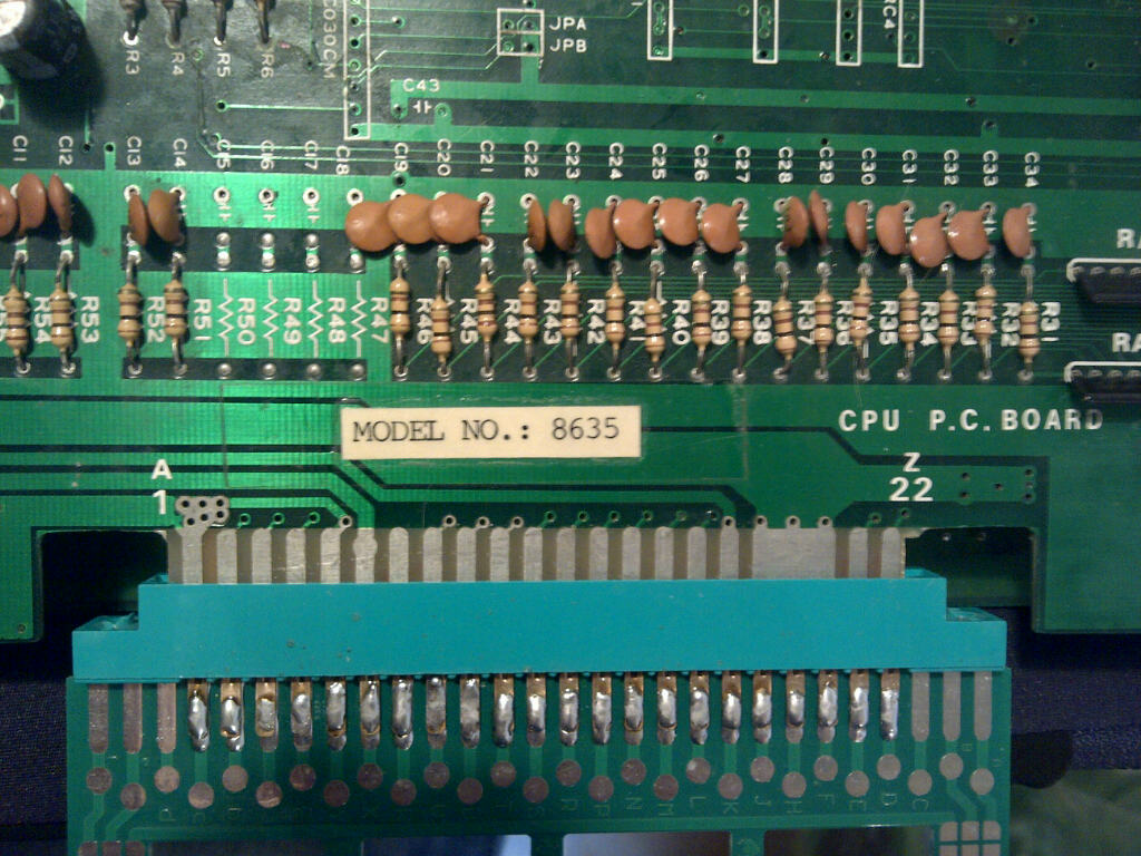
On my board pin 5 is connected to Ground (as per the screen shots above) so perhaps these connections are labelled incorrectly on the original pin-out at is should be
Speaker - on pin 5
instead?
[Judder - this was because I incorrectly had V, W & X connected to ground when they are actually +5V so achieved a short circuit - luckily the PC power supply I was using with the Super Gun has short circuit protection, so just shut itself down and waited for me to figure out where I was being stupid
]
I'm guessing with my adapter wiring Speaker + straight to ground, we get a short-circuit on the +5v as it simply flows straight to ground
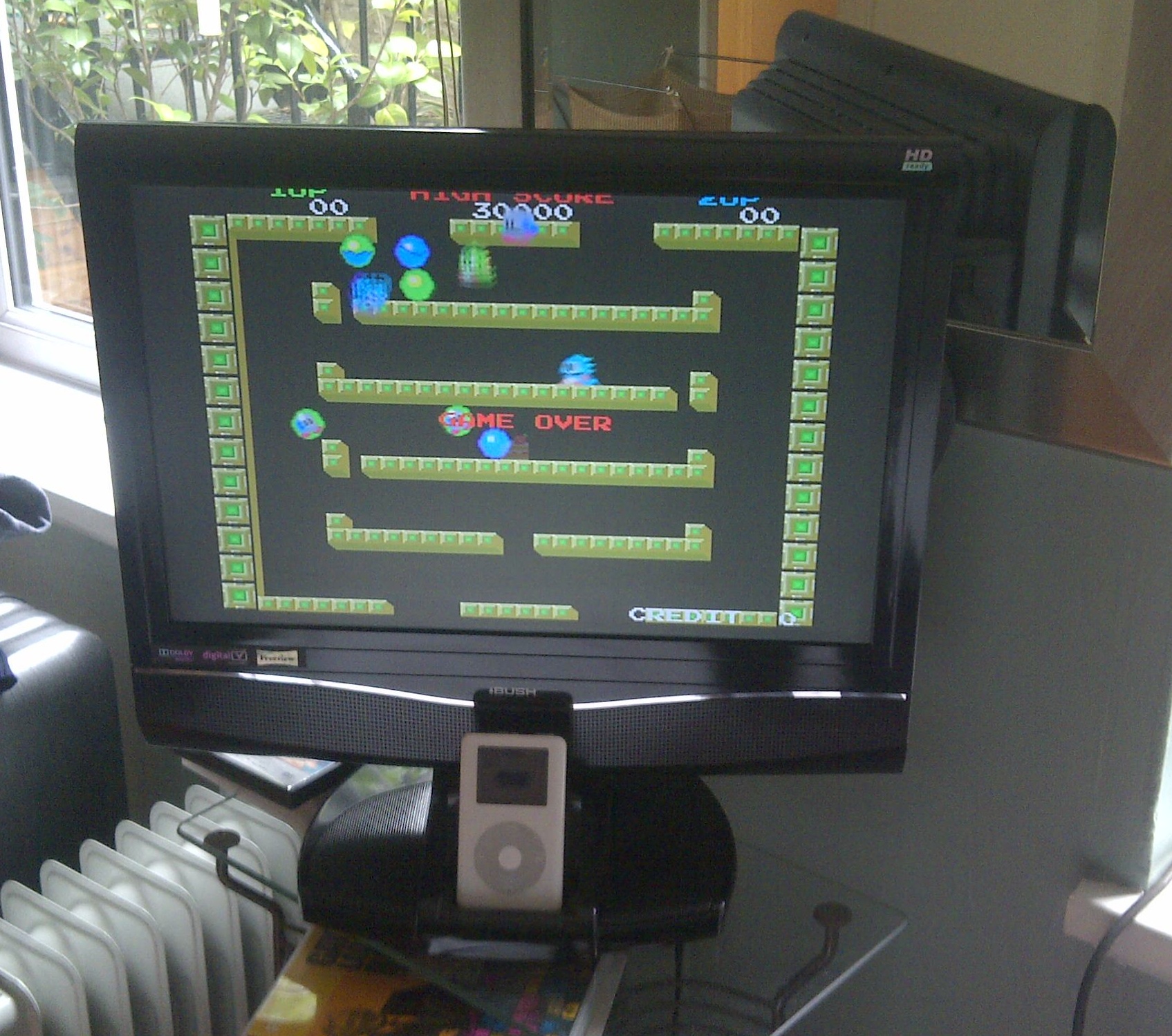
Here's the results so far (beautiful spaghetti!) and if everyone agrees I'll try un-soldering the Speaker + and Speaker - and test again to see if the board powers up this time.
BTW my board is the same / very similar to
this one on Jrok's site labelled as Super Bubble Bobble
http://jrok.com/boots/sbb_top.jpg
Judder2013-06-10 12:37:21