Another bootleg board from a job lot..

First thing for this was to make an adaptor for the edge connector. There is hardly any info online about this board and no edge connector info I could find which made sense for this pcb.
Sorted the basics - GND, +5v, +12v, RGB, sync, vid GND .. checked for shorts, all good .. First turn on and greeted with this ...

Visual check showed a few areas of small concern ...

Re-seated eprom 11 with the pin IN the socket - No change to the game - still garbage on the screen. But hoped this was going to be a really simple fix as it looked like eproms 1-4 had been put in in the wrong order... put them in the sockets which matched their numbers - again no change. weird. It was from this point I ended up in a world of confusion, burning sets of ROMs from different versions of the bootleg (there is a version called Force Break) and the positions they go on the board. Eventually worked it out and got a full set of roms for the bootleg version (brkthrubl) and got them in the board. The weird thing is that you do have to reverse the order of roms 1-4 (so rom 4 goes in socket 1, 3 in socket 2, etc) for the game not to crash and watchdog during the attract mode. So now the game boots but there are clearly issues ...

Backgrounds and Sprites are either not there or messed up. Text layer seems good though.... And every now and again it still crashes and when it does it watchdogs and then I get this screen ...

Ok so a RAM issue, but these numbers mean absolutely nothing to what's on the silkscreen. they make no sense that I can fathom, 8B, 11B, 14B ..
So then I spend ages probing chips on the top board, sometimes the watchdog kicks in then I get the RAM check screen, sometimes the game just reboots, I keep turning off and on and probing with a logic probe without really getting anywhere for about 20 mins and then out of nowhere I spot a high score screen on the monitor ... then garbage again ... then a bit of gameplay background ... then a title screen ..... and over the next 5 minutes of rebooting the game just seems to .. sort itself out, kind of !! without me really doing anything !

So I've no idea how this happened .. heat, bridging some pins, taking eproms out and putting back in again -maybe it was some corrosion in sockets that may have cleared, but now the background layer seems to be ok. I can't play a game because I've not hooked up coin up or controls so I've only got attract mode to go off but it now looks like only sprites are either missing or flashing up here and there and corrupted when they do ..

At this point I need to get to the bottom board because it's eproms 9, 10 and 11 which handle sprites and most of the board's RAM is there too ..

Spent quite a bit of time on this board, probing eproms, and chips surrounding them. without schematics you can spend a long time tracing signals, and I did. Without any joy.
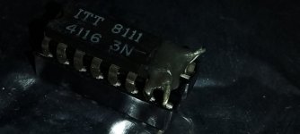
When I looked at the RAM chips (HY4808) aka 6116 RAM I noticed a leg on one of them was looking in a bad way .. also found a LS257 with a leg hanging on for dear life.

Here we go, problem solved I thought .... Err no, soldered them up and no change
First thing for this was to make an adaptor for the edge connector. There is hardly any info online about this board and no edge connector info I could find which made sense for this pcb.
Sorted the basics - GND, +5v, +12v, RGB, sync, vid GND .. checked for shorts, all good .. First turn on and greeted with this ...
Visual check showed a few areas of small concern ...
Re-seated eprom 11 with the pin IN the socket - No change to the game - still garbage on the screen. But hoped this was going to be a really simple fix as it looked like eproms 1-4 had been put in in the wrong order... put them in the sockets which matched their numbers - again no change. weird. It was from this point I ended up in a world of confusion, burning sets of ROMs from different versions of the bootleg (there is a version called Force Break) and the positions they go on the board. Eventually worked it out and got a full set of roms for the bootleg version (brkthrubl) and got them in the board. The weird thing is that you do have to reverse the order of roms 1-4 (so rom 4 goes in socket 1, 3 in socket 2, etc) for the game not to crash and watchdog during the attract mode. So now the game boots but there are clearly issues ...
Backgrounds and Sprites are either not there or messed up. Text layer seems good though.... And every now and again it still crashes and when it does it watchdogs and then I get this screen ...
Ok so a RAM issue, but these numbers mean absolutely nothing to what's on the silkscreen. they make no sense that I can fathom, 8B, 11B, 14B ..
So then I spend ages probing chips on the top board, sometimes the watchdog kicks in then I get the RAM check screen, sometimes the game just reboots, I keep turning off and on and probing with a logic probe without really getting anywhere for about 20 mins and then out of nowhere I spot a high score screen on the monitor ... then garbage again ... then a bit of gameplay background ... then a title screen ..... and over the next 5 minutes of rebooting the game just seems to .. sort itself out, kind of !! without me really doing anything !
So I've no idea how this happened .. heat, bridging some pins, taking eproms out and putting back in again -maybe it was some corrosion in sockets that may have cleared, but now the background layer seems to be ok. I can't play a game because I've not hooked up coin up or controls so I've only got attract mode to go off but it now looks like only sprites are either missing or flashing up here and there and corrupted when they do ..
At this point I need to get to the bottom board because it's eproms 9, 10 and 11 which handle sprites and most of the board's RAM is there too ..
Spent quite a bit of time on this board, probing eproms, and chips surrounding them. without schematics you can spend a long time tracing signals, and I did. Without any joy.
When I looked at the RAM chips (HY4808) aka 6116 RAM I noticed a leg on one of them was looking in a bad way .. also found a LS257 with a leg hanging on for dear life.
Here we go, problem solved I thought .... Err no, soldered them up and no change
Last edited: