Cosmic Guerilla PCB

aeroflott

A different league
Feedback
16 (100%)
Credits
1,061CR
OK a fresh thread for this.

I have a Cosmic Guerllia PCB that displays patterns but no game on screen:

IMG_20160910_163403_zpsflusaheg.jpg


The +12v LED is out on the PCB:

1473521534675_zpsebvhk4kv.jpg


The only visual thing I noticed was this bodged fuse holder. Removing the electrical tape reveals half the clip has snapped off.

1473521576778_zpsbxhrzuon.jpg


I'll replace that and report back. All fuses are good.

Any other suggestions of things to look at?

aeroflott2016-09-10 17:21:20
 

smarty

Ready Player One
vacBacker
Feedback
12 (100%)
Credits
1,305CR
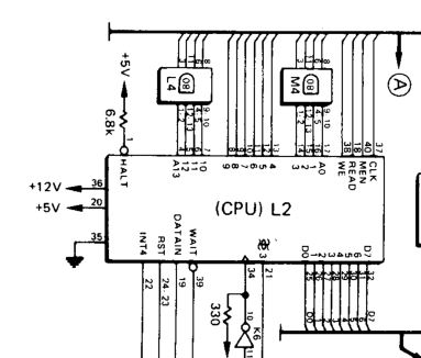
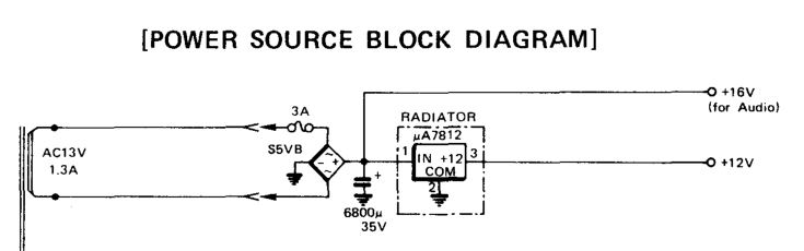
The Schematics show the 12V line going to the CPU, (Amongst other at a guess.) Surely you need to get the 12V line running before going further, the schematic for 12V shouldn't be difficult to work out.

CG_CPU.JPG


CG_12V.JPG


The AC voltage input go through a bridge rectifier to turn into DC voltage approx 16V for audio, that is then fed into the 7812 regulator to give a stable 12V.
 

aeroflott

A different league
Feedback
16 (100%)
Credits
1,061CR
OK so it wasn't the fuse holder.

Thanks for the above Smarty - all I see is "stuff". But are we saying that perhaps the 7812 might be the culprit? I shall be pulling you to one side tomorrow and asking questions.
 
G

Guests

Guest
Board is lacking +12V going by those LED's. Is there any 12V coming from the PSU? If not then I'd sort that first and go from there.
 

aeroflott

A different league
Feedback
16 (100%)
Credits
1,061CR
Soooo I replaced the 7812 regulator tonight and now the 12v LED is lit!

Sadly, the game isn't working. Blank screen.

Monitor is OK, game coins up (you can hear the counter move), but nothing's happening. Nothing displayed on screen.

I've not reseated any chips - might give that a go - clean the connector. Anything else obvious I should look at?

Thinking ahead - who can look at this for me?
 

philmurr

Active member
vacBacker
Feedback
48 (100%)
Credits
2,374CR
Can you measure the actual voltages on the board and make sure they're in spec

Then see what A0 to A13 and D0 to D7 are doing, see if there's any address and data bus activity
 
Top