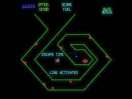
Defense Command (defender bootleg)

mickyc22

User
Feedback
1 (100%)
Credits
67CR
Anyone familiar with this board set, i have one and its failing to boot correctly so after some advice, i know its possible to run defender eproms on the board, but at present mine still has defense command in it. I also know there are 2 versions of this defence command and defense command mine is the latter with one ribbon cable. Google image below for reference.
It starts to boot get the boot pattern then nothing the 4 leds flash twice suggesting no standard errors but nothing on the screen, the test button on the eprom/sound board does kick off the defender type growl, and the bottom board button resets it.
i am aware of the defence command manual online but i know its somewhat different to my version although both are very similar to defender itself.
couple of my chips have lost their lettering so i like to compare with another board what they actually are, as i cant find any schematics for my version.
Any advice would be gratefully apricated.
IMG_3920.jpg
 

cliff_poole

Active member
vacBacker
Feedback
6 (100%)
Credits
1,069CR
I've got a working one of those, what chips do you need to know about ?.

For circuit diagram, it should loosely follow early Defender, except for component locations.

At least the RAM is all socketed. Try re-seating all the socketed chips first.
 

mickyc22

User
Feedback
1 (100%)
Credits
67CR
I've got a working one of those, what chips do you need to know about ?.

For circuit diagram, it should loosely follow early Defender, except for component locations.

At least the RAM is all socketed. Try re-seating all the socketed chips first.
thanks i dig out a picture of the chips im after in a bit, the ram wasn't socketed in mine but i have sweated them all out and tested them and now socketed them they were all fine, reseated all the other chips tested the cpu, checked voltages. i have been following the defender/defence command schematics both very similar but i notice the watchdog/reset input is different and it goes to a tied pin on an unmarked chip hence my shout out on here.
 

mickyc22

User
Feedback
1 (100%)
Credits
67CR
I've got a working one of those, what chips do you need to know about ?.

For circuit diagram, it should loosely follow early Defender, except for component locations.

At least the RAM is all socketed. Try re-seating all the socketed chips first.
pin 37 the reset from cpu tied to pin 16 and 17 on ic68 which is unmarked on mine
i assume its a 7411 going of other schematics but it shouldnt be a tied pin, hence im confused...

also ic 69 is unmarked

WhatsApp Image 2023-10-02 at 12.40.09.jpeg
 

philmurr

Active member
vacBacker
Feedback
48 (100%)
Credits
2,374CR
I know it doesn't help you identify those chips, but is the reset actually causing you problems?

As it part boots that shows the reset and watchdog were working properly. I'd be inclined to check the EPROMs as the next step.

Then check the NVRAM, count240 signal and the vertical position counter


Edit: more information
 
Last edited:

mickyc22

User
Feedback
1 (100%)
Credits
67CR
I know it doesn't help you identify those chips, but is the reset actually causing you problems?

As it part boots that shows the reset and watchdog were working properly. I'd be inclined to check the EPROMs as the next step.

Then check the NVRAM, count240 signal and the vertical position counter


Edit: more information
im just trying to trace what is what, i agree the watchdog and reset are probably fine im just curious what those chips are, i've tested all the ram chips they are fine, swetted them out put them in a ram tester and socketed them back in, Im pretty sure the eproms are fine too as i get the 4 leds flash twice, correct me if im wrong dont they display a pattern if there is an eprom at fault?
 

mickyc22

User
Feedback
1 (100%)
Credits
67CR
I know it doesn't help you identify those chips, but is the reset actually causing you problems?

As it part boots that shows the reset and watchdog were working properly. I'd be inclined to check the EPROMs as the next step.

Then check the NVRAM, count240 signal and the vertical position counter


Edit: more information
count240 signal and the vertical position counter, could you give more details on this please bit beyond my knowledge
 

philmurr

Active member
vacBacker
Feedback
48 (100%)
Credits
2,374CR
count240 signal and the vertical position counter, could you give more details on this please bit beyond my knowledge
Download the Defender theory of operation https://www.robotron-2084.co.uk/manualsdefender.html

It mentions them both, you'll have to trace back which are the right chips on your board. But basically check that you can see them being selected (vertical position count is continuous but Count240 is just after the LEDs flash)
 

mickyc22

User
Feedback
1 (100%)
Credits
67CR
Download the Defender theory of operation https://www.robotron-2084.co.uk/manualsdefender.html

It mentions them both, you'll have to trace back which are the right chips on your board. But basically check that you can see them being selected (vertical position count is continuous but Count240 is just after the LEDs flash)
thanks been going through the theory manual not got as far as count240 will look into that
 

mickyc22

User
Feedback
1 (100%)
Credits
67CR
Many thanks @cliff_poole I also got a pic from elsewhere that confirms the same as you what you have posted, not what i was expecting, im curious do you have chip in ic53 i dont but the person i got the pic off does im guessing his may be a different revision as also has few extra caps. i do belive this was a working board in the cab before it went into storage and i bought it
comparison.png
 

cliff_poole

Active member
vacBacker
Feedback
6 (100%)
Credits
1,069CR
Yours has a 7404 at IC54. I imagine they decided they could do away with the extra chip. Presumably it used to work so I doubt it will be the cause of any problems.
The missing caps have one end connected to ground, maybe they were added because of the different manufacturer of the chips, slightly different specs. Again, if it was working before ignore it for now.

Worth still checking the ROMs anyway, they may have bypassed the ROM check in code. Apologies if this is way too obvious, but is the board getting -5V and +12V.
 

Kingpin

User
Feedback
1 (100%)
Credits
113CR
If you read the (E)PROM data you can verify the binary contents using MAME with the ROMIDENT command (for example mame.exe -romident romfile.bin).
 

mickyc22

User
Feedback
1 (100%)
Credits
67CR
I didn't, I put this board aside and opted to put in a 19 in 1 locked into defender and spliced in a jamma connection, end of the day the cab was a bootleg/clone so dont think it matters. The original board and harness still in the cab, but myself im happy with it running the 19 in 1. plan to do away with the 4 way joystick put in a 2 way and add a thrust button.
how it was found
Screenshot 2023-10-23 125026.png
now with custom defender marquee
WhatsApp Image 2023-10-23 at 12.35.38 (1).jpeg
 
Top