Diodes?

Ronnie Dent

Active member
vacBacker
Feedback
15 (100%)
Credits
1,206CR
Looking for some advice?

I have a board that has a diode fitted from the schematic it should be 1N5960B but has a BZX85C fitted would that be okay?

And I have a shorted 1N4742A 12v 1 watt Zener what else could I use in it's place? could I use a 4744? sorry I meant 4764 1 watt 100v

Thanks for any advice

Ronnie
Ronnie Dent2015-05-23 15:58:48
 

obcd

Active member
Credits
3,830CR
For the 12V 1W zener, you will need another 12V zener of at least 1W. The wattage can be higher but the voltage need to be correct.

The BZX85C is a zener as well. It should also have an additional number indicating the voltage.

The 1N5960B doesn't give much usefull when searching for it on google. Since you know it's the original that should be there, I assume you have the schematics. So, if that's a zener as well, check it's voltage and power rating and see if that BZX85C has the same voltage, and the same or a higher power rating (wattage).
 

Ronnie Dent

Active member
vacBacker
Feedback
15 (100%)
Credits
1,206CR
obcd said:
For the 12V 1W zener, you will need another 12V zener of at least 1W. The wattage can be higher but the voltage need to be correct.

The BZX85C is a zener as well. It should also have an additional number indicating the voltage.

The 1N5960B doesn't give much usefull when searching for it on google. Since you know it's the original that should be there, I assume you have the schematics. So, if that's a zener as well, check it's voltage and power rating and see if that BZX85C has the same voltage, and the same or a higher power rating (wattage).

thanks just noticed the voltage rating after the BZX85C that being 100v the schematic was hard to read so may have that number wrong but it's high voltage reg of either -98 or -110

Cheers Ronnie
 

obcd

Active member
Credits
3,830CR
I assume (but that is never good for repairs) that the output voltage of the circuit will be 10V lower as well. It's possible that the circuits that use that voltage will still work fine on that lower voltage. If a 110V zener is difficult to find, you could use a 50V and 60V zener in serie. The combined voltage of these is also 110V An extra 10V zener in serie with the 100V one should work as well.

Since someone replaced the diode, it might mean that things probably worked with the slightly lower zener voltage, so I shouldn't focus on that difference.
 

Ronnie Dent

Active member
vacBacker
Feedback
15 (100%)
Credits
1,206CR
Thanks again, the power supply is for a pinball these voltages driving the dmd display which does not work but I suspect the display is out gassed, I blew it trying to test the display! With jumper wires direct to the pins of the display as per a service bulletin by the maker, but accidentally one of my croc clips touched ground! But what I never noticed instead of a 500 mili amp fuse it had a 2 amp fitted so wiped the 2 diodes and the transistor mje350. As far as I know the 3 high voltages need to be close to spec to drive the dmd? Will see what diodes I have I have a few variants of BXZ85C hoping I can use one of those for the 12v 1 watt? I did see some 110v zener on eBay

Thanks Ronnie
 

obcd

Active member
Credits
3,830CR
If I remember well, the difference between the 2 high voltages on such a display has to be correct and stable. The value of the voltages is not so critical. So, for instance 100V and 110V should be fine, but 110V and 120V should be fine as well (the numbers are just for an example) We never had much problems with those displays on bally pinballs, but the "sega stern" ones seem to outgass after 1 - 2 years. (They do run 14 hours/day)We even decided to replace it with a led module display. Problem with that was that we couldn't find a decent big enough red filter to place in front of that led display. Outgassed displays usuall start by giving less light, specially at the edges of the display. After a period of operation, things start to become better. There has to be a significant difference in the way those displays are driven between Bally and Stern that explains the lower MTBF of those last, but I never had time to make a good study of it. It wouldn't suprise me that Stern uses a faster refresh rate which allows different pixel intensities on those displays. Bally probably simply drives a pixel on or off. Just measure the voltages on your regulation pcb before you connect another display to be sure you don't fry it. They are expensive.
 

Ronnie Dent

Active member
vacBacker
Feedback
15 (100%)
Credits
1,206CR
This one is a data East small 128x16 display, further checking I have an open large ceramic 10 watt resistor R14 value 3.9k but schematic lists it as 4k 10 watt struggling to find a replacement ?

This display was dead on arrival a voltage check showed as good so the board seemed to be okay until I fried it! So chances are the display is out gassed or otherwise faulty.

I do have some 100v Zener diodes and some 12v ones I wonder if I should stick with the 100v or order some 110v one's, now need to source that big resistor and I guess check the other smaller one's in that circuit

Thanks Ronnie
 

obcd

Active member
Credits
3,830CR
I hope you are able to find such a 128 x 16.

128 x 32 was more frequently used if I remember well.

Just replace the resistor with another 3K9 10W. The 100 ohms won't make the difference.
 

Ronnie Dent

Active member
vacBacker
Feedback
15 (100%)
Credits
1,206CR
Thanks, already got a new 128x16 pinled display but at a cost of £180! But it won't be going near the pinball until I have the psu right, but I think it only uses the 5 volts? And probably the 12v.

Still looking for the resistor 5 watts seems to be the norm?

Thanks Ronnie
 

obcd

Active member
Credits
3,830CR
If you replace the display with a led version you indeed won't need the high voltage anymore. You might need a separate 5V supply as the leds draw some current from the 5V supply and the pinball supply isn't designed to deliver that additional current on it's 5V They even say you need to disconnect the high voltages needed for the VFD as they could damage the led display.
 

Ronnie Dent

Active member
vacBacker
Feedback
15 (100%)
Credits
1,206CR
Well the display plugs directly to the old power plug and ribbon connector but it came with no instructions at all! So will need to look into that, no mad rush as I'm at the early stages of a full refurb of the pin. Like I said would rather have the power supply fully working even if I need to pull the fuses to fit the led display.

For the life of me I can't find 110v 5 watt Zener diode? The only one on eBay was 1.5 watt. Going to have to use as you suggested one 100v in series with a 10v neither of which I have!

Thanks Ronnie
 

obcd

Active member
Credits
3,830CR
The high voltage pins might be "no connect" on the led display, but it's also possible they are used to connect the 5V As it needs more current, they might have used multiple pins to connect that.

If I remember well, they don't need 12V either. They work with a 5V only. This doesn't mean that your display couldn't be different.

You might get your display going first, as the selftests can be very usefull for the rest of the repairs.
 

Ronnie Dent

Active member
vacBacker
Feedback
15 (100%)
Credits
1,206CR
Just looked on pinled web site has instructions there, advises to remove hv fuses when fitting new display. As you remembered only uses 5v.

Wanted to get the electronics fixed before stripping play field for a much needed clean polish new rubbers etc. some of the fuse holders fell apart on the psu as well as a badly burned gi connector. But I have made more work for myself by blowing the hv
smiley18.gif
 

Ronnie Dent

Active member
vacBacker
Feedback
15 (100%)
Credits
1,206CR
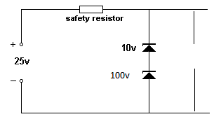
I have ordered some 100v and 10v zeners just want to double check the
way to fit them in series? this was just a diagram from google so supply
volts is not right but wondered about the diode placing!

Thanks Ronnie

Zener.gif
 

obcd

Active member
Credits
3,830CR
Yes, that's how it should be done. Position of 100V and 10V one doesn't matter.

Not clear why you would repair that hv as you don't need it anymore if you install a led display.
 

Ronnie Dent

Active member
vacBacker
Feedback
15 (100%)
Credits
1,206CR
obcd said:
Yes, that's how it should be done. Position of 100V and 10V one doesn't matter.

Not clear why you would repair that hv as you don't need it anymore if you install a led display.

Thanks for confirming that

Yes it seems daft to repair it, but I have 2 reasons if in the future me or someone else should want to go back to hv display then they can, the other reason is to see if the extra -10v will light the old display before I change it out, probably won't but maybe the old one will live some?

Thanks Ronnie
 

obcd

Active member
Credits
3,830CR
Makes sense.

You are sure the pinball cpu is working normally?

If you activate a switch like one of the slingshots, it's magnet is activated as expected?

The reason I am asking is because without working cpu, you wouldn't have a display as well.
 

Ronnie Dent

Active member
vacBacker
Feedback
15 (100%)
Credits
1,206CR
Because the pinball was stored for many years all I have done is power it up but it does go into attract mode with music etc and lights flashing as you would expect, diagnostic leds on cpu display normal for game running, but I never coined the game up most of the rubbers have perished and snapped. but once I have rebuilt the psu I will try that but confident it will start a game.

Thanks Ronnie
 
Top