
Hi, So I have had this cab for about a year and not had much of a chance to get working on it. Finally getting around to it and was hoping someone could point me in the right direction for the wiring inside the cab.
I got the cab as a project. It has all of the plastics and controls as well as the transformer, CRT, untested MIDI drive board and a bunch of wiring. At the moment I am wanting to use the cab with a PC for emulating racing games and I have the correct FFB board from gamoover to hook the controls up to the PC.
I am going to make my own wiring for the controls so as not to hack up any of the existing wiring (I have the crimps and AMP connectors here).
My first priorities are: Get power to the CRT, get power to the MIDI drive board and get the MIDI board connected to the steering. The PC should be easy enough to wire up. I have attached a few photos to help out.

What is that connector/fuse for on the orange/blue pair of wires and what voltage should I be expecting out of there? I am assuming one pair from that transformer should be 110 and one 240?
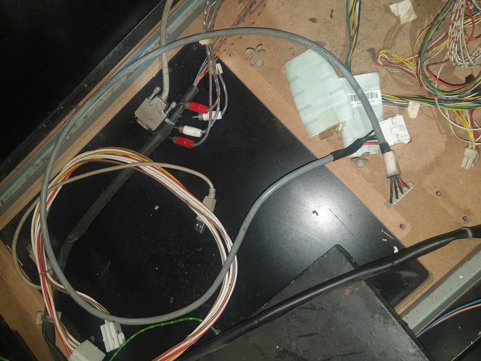

I assume the yellow wire that leads on to the pink and light blue wire is the connector that goes straight into the MIDI drive board at CN5? It looks like it should fit - I assume this board should be running at 110v?
To connect the drive board it looks like the thick gray cable connects CN4 on the drive board to the steering wheel and both of those connectors look like they match up - I just want to double check that before I do anything stupid.
I have not even powered the cab on to test voltages yet but hope to make a start this week. I am trying to get a clearer picture of how things are meant to be connected before making a start.
Thanks in advance for any help - hope it all makes sense. I have had a look at the service manual and although they are great for parts lists they don't really seem to cover the wiring in the cabs.
Gordon
I got the cab as a project. It has all of the plastics and controls as well as the transformer, CRT, untested MIDI drive board and a bunch of wiring. At the moment I am wanting to use the cab with a PC for emulating racing games and I have the correct FFB board from gamoover to hook the controls up to the PC.
I am going to make my own wiring for the controls so as not to hack up any of the existing wiring (I have the crimps and AMP connectors here).
My first priorities are: Get power to the CRT, get power to the MIDI drive board and get the MIDI board connected to the steering. The PC should be easy enough to wire up. I have attached a few photos to help out.
What is that connector/fuse for on the orange/blue pair of wires and what voltage should I be expecting out of there? I am assuming one pair from that transformer should be 110 and one 240?
I assume the yellow wire that leads on to the pink and light blue wire is the connector that goes straight into the MIDI drive board at CN5? It looks like it should fit - I assume this board should be running at 110v?
To connect the drive board it looks like the thick gray cable connects CN4 on the drive board to the steering wheel and both of those connectors look like they match up - I just want to double check that before I do anything stupid.
I have not even powered the cab on to test voltages yet but hope to make a start this week. I am trying to get a clearer picture of how things are meant to be connected before making a start.
Thanks in advance for any help - hope it all makes sense. I have had a look at the service manual and although they are great for parts lists they don't really seem to cover the wiring in the cabs.
Gordon


