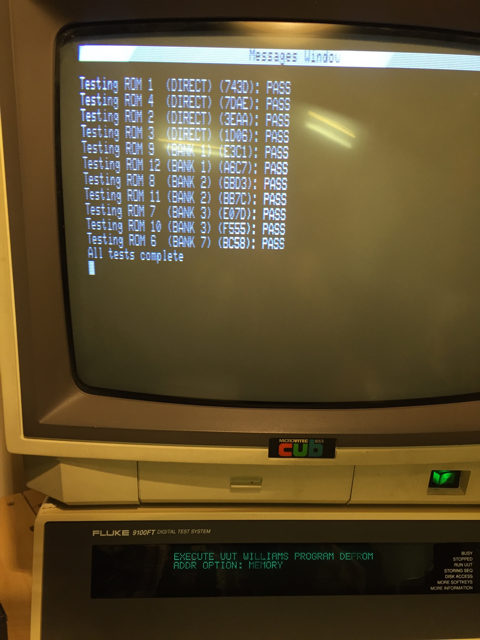
I've got an early series Defender on the bench at the moment that crashes as soon as it comes out of rug test. I've read through the theory of operation and understand how the memory is working in relation to the screen etc., in terms of which 4bit values related to which positions on (and off) the screen etc.
I have put all new 4116 RAM in the board and still no dice. I've been over it and can't see anything glaringly obvious thats wrong so I'm trying to be a bit more clever about this and test it properly. I did spot a 74139 that I haven't checked yet so I need to do that, but can someone confirm if it is possible to test the RAM using the following, or if the address / bit mapping is more convoluted?
In particular, I'm not sure if using a Fluke is possible at all because of timing, or if I need to do something to setup the board for testing. Ie, do I HAVE to disable watchdog or can I just set the Fluke to ignore it (I've done both). Do I need to write somewhere to enable RAM access? (I don't think so, that's for the banked ROMs).
Bank 1 (Column 4)
0-3FFF, Mask 1 - 4L
0-3FFF, Mask 2 - 4M
0-3FFF, Mask 4 - 4N
0-3FFF, Mask 8 - 4O
0-3FFF, Mask 10 - 4P
0-3FFF, Mask 20 - 4Q
0-3FFF, Mask 40 - 4R
0-3FFF, Mask 80 - 4S
Bank 2 (Column 5)
Repeat for 4000-7FFF
Bank 3 (Column 6)
Repeat for 8000-BFFF
I'm aware that the sockets could be crap, but that's the point of wanting to do the RAM test so that I know which of the 24 chips I need to focus on if at all possible (if any, I really am NOT convinced that it's RAM at fault). At the moment, whatever RAM test I do, I get "Cannot Write" at the lowest and highest address, if I push through with 'continue' the RAM test will proceed after (I think) one more error.
I'm really not having much luck with repairs at the moment!
I have put all new 4116 RAM in the board and still no dice. I've been over it and can't see anything glaringly obvious thats wrong so I'm trying to be a bit more clever about this and test it properly. I did spot a 74139 that I haven't checked yet so I need to do that, but can someone confirm if it is possible to test the RAM using the following, or if the address / bit mapping is more convoluted?
In particular, I'm not sure if using a Fluke is possible at all because of timing, or if I need to do something to setup the board for testing. Ie, do I HAVE to disable watchdog or can I just set the Fluke to ignore it (I've done both). Do I need to write somewhere to enable RAM access? (I don't think so, that's for the banked ROMs).
Bank 1 (Column 4)
0-3FFF, Mask 1 - 4L
0-3FFF, Mask 2 - 4M
0-3FFF, Mask 4 - 4N
0-3FFF, Mask 8 - 4O
0-3FFF, Mask 10 - 4P
0-3FFF, Mask 20 - 4Q
0-3FFF, Mask 40 - 4R
0-3FFF, Mask 80 - 4S
Bank 2 (Column 5)
Repeat for 4000-7FFF
Bank 3 (Column 6)
Repeat for 8000-BFFF
I'm aware that the sockets could be crap, but that's the point of wanting to do the RAM test so that I know which of the 24 chips I need to focus on if at all possible (if any, I really am NOT convinced that it's RAM at fault). At the moment, whatever RAM test I do, I get "Cannot Write" at the lowest and highest address, if I push through with 'continue' the RAM test will proceed after (I think) one more error.
I'm really not having much luck with repairs at the moment!