Galaxian Problem

edget2000

Active member
Feedback
7 (100%)
Credits
135CR
Hi

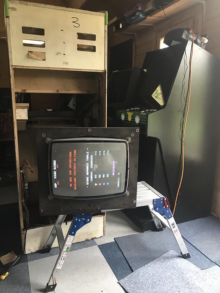
Wondered if someone can point me in the right direction with my problem. Been fixing a Galaxian that ended up having a dodgy switcher. When I went to put the original PCB back in I had a white line across the bottom of the screen that does occasionally scroll down the screen as well. The shadow/blur in the middle of the monitor screen is my reflection it does look better than that but the screen burn is bad unfortunately.

IMG_0497a.jpg


So i thought I would go grab my pukka backup PCB and throw it in the cabinet while I found a fix for the white line. So I put the backup on my jamma rig just to make sure it was okay before I put it in the cabinet and it did perfectly as you can see below.

IMG_0498a.jpg


But when I put it in the cabinet below was the result
smiley19.gif
and the sounds it making were all weird as well.

IMG_0499a.jpg


So 2 questions really.

1. Is it bad memory or bad roms that might cause the white line on the bottom of the screen on my original PCB?

and

2. Why doesn't the new pcb work in my cabinet when it does in the jamma rig?

cheers in advance

Tony
 

RGP

Meeter & Greeter
Feedback
5 (100%)
Credits
2,039CR
Are one or both your PCB's DC modded?

Looking at the one on your bench it should be accepting AC because the diodes are still in place.

Is your cab giving DC or AC to the board.

If you take your backup PCB that had the bad output and put it back on the bench does it still work normally?
 

edget2000

Active member
Feedback
7 (100%)
Credits
135CR
RGP said:
Are one or both your PCB's DC modded?

Looking at the one on your bench it should be accepting AC because the diodes are still in place.

Is your cab giving DC or AC to the board.

If you take your backup PCB that had the bad output and put it back on the bench does it still work normally?
Hi James

As far as I can see the 2 PCB's look identical and no noticeable mods on them. Only thing I've noticed is that the roms might be different as the PCB with the white line across the screen displays the NAMCO logo. It also works fine in my Jamma rig except for the white line.

When I put my backup PCB back into my JAMMA rigs it works fine.

I'm gonna have a look at my power/harness setup to see if anything has been hacked and do some research on "DC Modded"
smiley5.gif


cheers

Tony
 

Judder

Active member
Feedback
2 (100%)
Credits
1,009CR
Hi guys - just a helpful nod but I believe the AC circuit on Galaxians can take DC quite happily as the AC part is just redundant in that case - thought it might help with your problem elimination!

"Galaxian PCB Pinout and using Galaxian in a Pacman Cabinet.

Power supply: Galaxian gets its input voltages from a 7 volt/12 volt AC transformer. Once this power is on the pcb, it is converted to 5 volts DC and 12 volts DC (essentially the power supply is built-in to the logic board).

BUT you can hook up a standard switching power supply, which supplies 5 volts DC at 7amps (or greater), and 12 volts DC to the Galaxian 7 volt AC and 12 volt AC input lines. This causes no problems. My only suggestion is that you turn the 5 volt adjuster all the way up on the switching power supply. This will make the output voltage from the switcher close to 6 volts. The Galaxian logic board will draw this voltage down to 5 volts."

http://www.pinrepair.com/video/galaxian.htm

Alex

Judder2017-05-13 11:48:20
 

edget2000

Active member
Feedback
7 (100%)
Credits
135CR
Judder said:
My only suggestion is that you turn the 5 volt adjuster all the way up on the switching power supply. This will make the output voltage from the switcher close to 6 volts. The Galaxian logic board will draw this voltage down to 5 volts."

cheers for this. I went and set it to 5.1v when I installed the new switcher. Weird that the faulty board still displays okay (except the white line) but my supposed pukka board doesn't at that voltage.

cheers

Tony
 

edget2000

Active member
Feedback
7 (100%)
Credits
135CR
RGP said:
Are one or both your PCB's DC modded?

Looking at the one on your bench it should be accepting AC because the diodes are still in place.

Is your cab giving DC or AC to the board.

If you take your backup PCB that had the bad output and put it back on the bench does it still work normally?

Many Thanks James you got me on the right track. Went and had a closer look at the old pcb with the fault and there were the 4 shorts. Checked my spare and it wasn't modded, luckily had a look through my box of boards and I had a another spare pcb that work and was modded and low and behold I got the image below.

Thanks to James and all that gave me advice above, I actually feel like I learned a few things today and my Galaxian repair is complete, though the k4500 monitor needs a tweak. Just got to give it a clean now
smiley1.gif
but first the rugby European final and beer.....

IMG_0502a.jpg
 
Top