Hantarex Polo 28 No Picture

Jon-A-Tron

Active member
Feedback
2 (100%)
Credits
233CR
Hello.

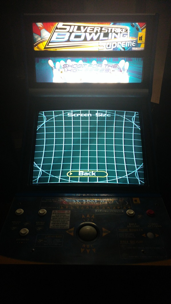
So I bought my 1st cabinet last month (Silver Strike Supreme Bowling) with a dead Polo 28" Monitor.

The game works perfect with another monitor plugged into the VGA.

There is neck glow when powered up but no static on the front of the screen. At first I thought it could be a faulty flyback but, would this give me neck glow if it was faulty?

After searching high and low for some diagrams I found a pretty useful flow chart here;

http://gc339.free.fr/NoticesMoniteurs/Hantarex/Polo/POLO.FlowChart.jpg

Going through the steps,

Blank Screen - Yes

Fuse F101 - Good

Clicking? - Not that I can hear

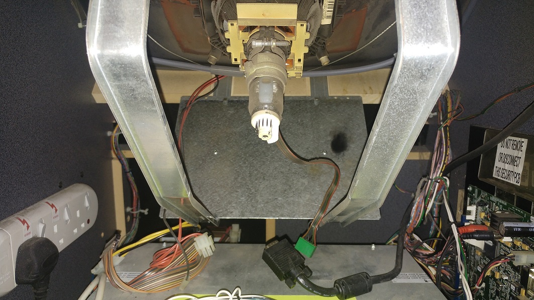
B+ at TP6. Now this stumped me for a long time. I could not find TP6 anywhere on any board or diagram. I eventually found a description of where to test from another forum after countless searches. I tested on the Green 6-pin Yolk connector Black link cable and got 126vDC. So this is low.

So then it was time to remove the Chassis.

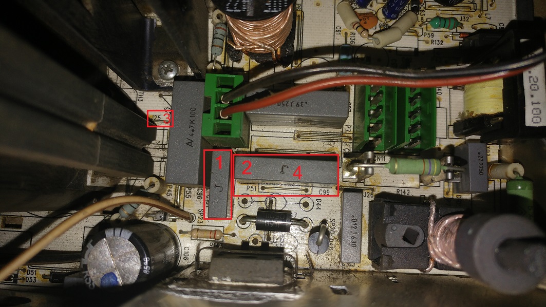
On removal I found..

FaultDiag5.jpg


And the back of the chassis..

FaultDiag3.jpg


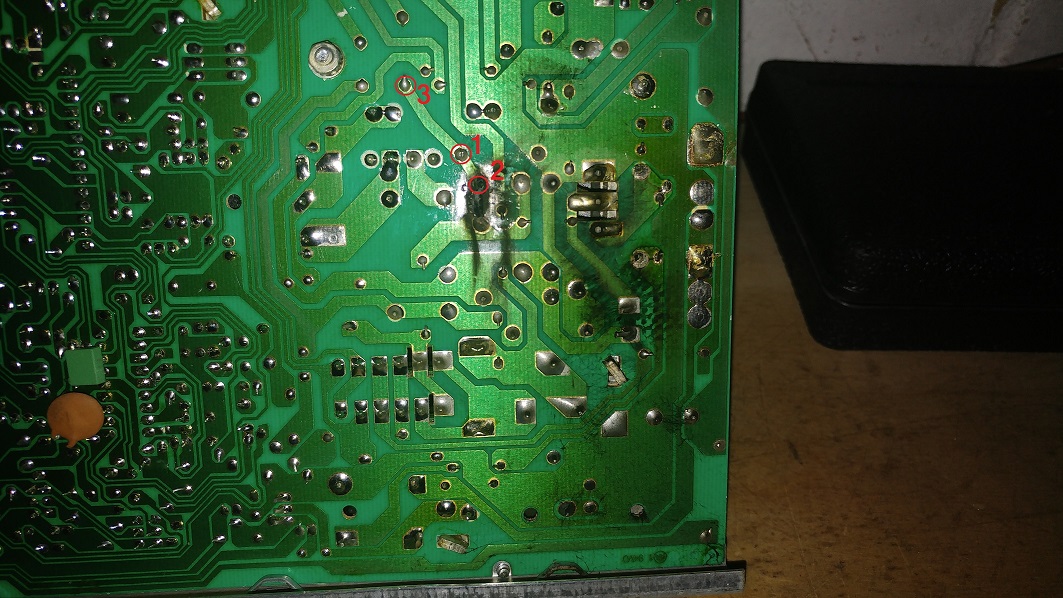
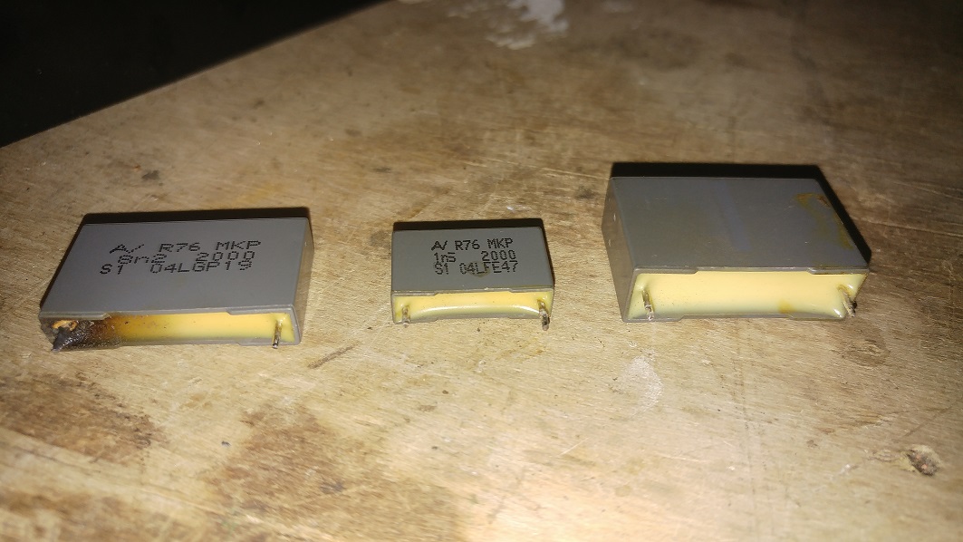
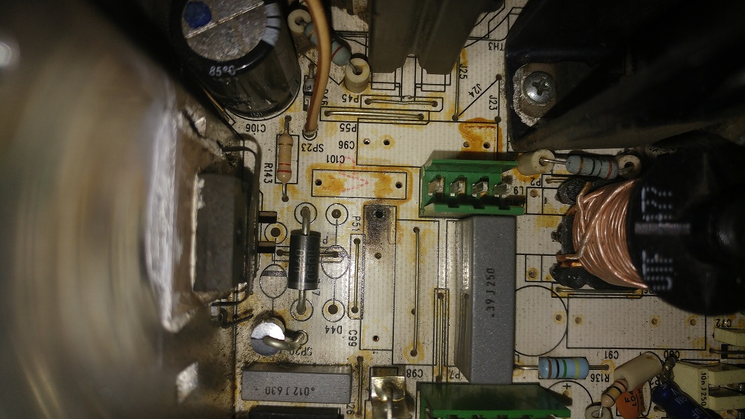
Component Side. Edit; Marked the wrong Cap (C96) last time. Thanks to MKL for the spot.

FaultDiag8.jpg


Circuit.

FaultDiag1.jpg


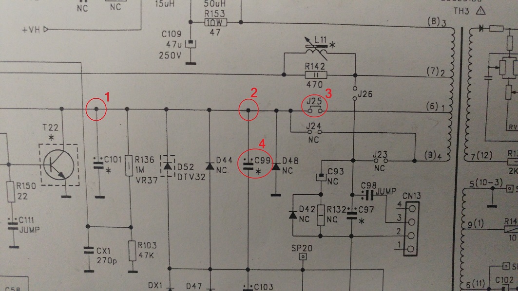
Pad 2 for the C99 capacitor has been completely blown out along with the trace up the circuit. The voltage is being held at J25.

My plan is to replace C99 and solder jumper wires from 1-to-2 and on to the pad just below in place of the trace. The rest of the board looks pretty good so I think it might have been a short to C99.

What do you think?

Should I look to replace other parts around this point as well as C99?

Or should I just go ahead with this fix 1st and see what result I get?

Either way i'll keep this updated so hopefully it can help other with this monitor in the future.

JT

If anyone knows a better place to test the B+ on this let me know, cheers.

JonTron2016-11-06 20:43:20
 

big10p

Coins detected in pocket!
vacBacker
Feedback
12 (100%)
Credits
5,605CR
I've had a blown HV cap blow a hole in the board like this, and managed to repair it using jumper wires where the traces had been destroyed. Worked fine. Make sure you use thick wire for the jumpers, though. After fixing, test you're getting continuity where you should be, all around the repair.
 

MKL

Newbie
Credits
83CR
That flowchart is for the 15khz Polo, you have a polo star (15-25-31khz). And your markings on the pics are quite off...
 

Jon-A-Tron

Active member
Feedback
2 (100%)
Credits
233CR
big10p said:
I've had a blown HV cap blow a hole in the board like this, and managed to repair it using jumper wires where the traces had been destroyed. Worked fine. Make sure you use thick wire for the jumpers, though. After fixing, test you're getting continuity where you should be, all around the repair.

Thanks. Yeah looking at the size of the traces around this area i'll be sure to put some heavy guage in there. I'll do some research on tbe output voltage of that leg of the transformer and work out what it should be.

MKL said:
That flowchart is for the 15khz Polo, you have a polo star (15-25-31khz). And your markings on the pics are quite off...

Flow chart was the best i could find to be honest. If you have a link to a better one id be greatful. Really i was just using it to help me figure out where to start.
Where are my markings off? I did all common continuety tests to all the points i've marked with correct results.
JonTron2016-11-06 10:36:54
 

obcd

Active member
Credits
3,830CR
The capacitor could be bad, but the damage can also be caused by sparking due to a bad soldering. Most multimeters nowadays have an option to measure capacitors. If those capacitors go bad, you should at least check the HOT as well. If the connection to the HOT became disconnected, it could explain what you (don't) see as well. A shorted hot would produce the clicking sound in the power supply.
 

Jon-A-Tron

Active member
Feedback
2 (100%)
Credits
233CR
obcd said:
The capacitor could be bad, but the damage can also be caused by sparking due to a bad soldering. Most multimeters nowadays have an option to measure capacitors. If those capacitors go bad, you should at least check the HOT as well. If the connection to the HOT became disconnected, it could explain what you (don't) see as well. A shorted hot would produce the clicking sound in the power supply.

Yeah, I was thinking maybe the game got moved while it was still powered on and the board bounced and shorted the soldered pad to the chassis frame but, who knows. The link cable J25 that comes from the Flyback Transformer shows no sign of damage and I suspect that would have been the weak point if the fault originated there.

Thanks for the info, I'll check the HOT for sure. Didn't have the ticking so maybe your right about it being disconnected. The blown trace has disconnected a whole section of the board so it could be hiding lots of little issues.
 

MKL

Newbie
Credits
83CR
JonTron said:
Flow chart was the best i could find to be honest. If you have a link to a better one id be greatful. Really i was just using it to help me figure out where to start.

I wouldn't use the flowchart of a monitor to figure out things on a different monitor. The fact that they're both called "Polo" doesn't make them the same monitor.

JonTron said:
Where are my markings off? I did all common continuety tests to all the points i've marked with correct results.

Your marking "1" is on C101 in the solder side pic but on C96 in the parts side pic.

Your 1, 2, 3 in the schematics pic should be one thing, yes but you want to make sure the whole part, which is the collector pulse line (goes from the collector of the HOT T22 to a pin of the flyback), is not shorted to ground. If it is you need to remove and replace the component(s) which is (are) causing the short.
 

Jon-A-Tron

Active member
Feedback
2 (100%)
Credits
233CR
MKL said:
Your marking "1" is on C101 in the solder side pic but on C96 in the parts side pic.

Your 1, 2, 3 in the schematics pic should be one thing, yes but you want to make sure the whole part, which is the collector pulse line (goes from the collector of the HOT T22 to a pin of the flyback), is not shorted to ground. If it is you need to remove and replace the component(s) which is (are) causing the short.

You're absolutely right, I marked the wrong Cap on the component side, doh. I'll re-do that pic asap.

I've checked the HOT T22 Collector to ground and i'm getting around 1M ohm. This looks to be correct given the 1M R123 (reading 880k in circuit) and the 47k R103 (reading 45k in circuit) are on the line to ground. I'm also getting 1.2ohm at the Base (1ohm R151 + 0.2ohm on the coil of TH2). Emitter is 0.1ohm to ground.

I've removed the Caps C99/C101/C96.

FaultDiag6.jpg


Component Side Damage.

FaultDiag7.jpg


Damage does look to be isolated to that C99 Capacitor and the trace.

One thing that is strange is that C99 should be a 7.5nF Cap and the one I pulled out was 8.2nF. C103 should also be 15nF and looks like a 12nF installed. Rest of the caps match the diagram for the 25"-28".

What's the consensus, like for like or change to match the diagram?
 

singy1uk

User
Credits
119CR
Change like for like.manufactures change certain components on different models of the same chassis for different configurations .your schematic may have a note to say which were changed.
 

obcd

Active member
Credits
3,830CR
Maybe the component values aren't very critical.

Those capacitors might be there against high voltage spikes when the HOT cut's the current flow.

Just make sure you find some with high enough voltage specifications. If the chassis worked with the values that were in, I would put the same values in again and not the ones from the schematics. it's possible that someone did some measurements on the chassis and figured out that a bit higher capacitance worked better.
 

Jon-A-Tron

Active member
Feedback
2 (100%)
Credits
233CR
singy1uk said:
Those cap changes are made for a 34" tube along with other components.its noted on the schematic for the polo star chassis.

For the C99 the 8n2 is for the 34" tube. For the C103 I've got a 12nF, it should be 18nF for the 34".

The rest of the caps have the values correct for the 25"-28" so i'll go along with what obcd said.

These caps are a real pain to find. Sent an email to Mouser Electronics who took over Arcotronics who made these types of caps. Hopefully they have an alterative.

JonTron2016-11-07 00:36:44
 

MKL

Newbie
Credits
83CR
Ignore the schematics. The values you have on your chassis are the correct ones. All my 25" chassis are the same.
 

tb2000

Active member
Feedback
4 (100%)
Credits
3,150CR
I may have missed you mention it but have you found Polostar schematics now? What you have here is a common problem, I've seen it many times on Hanty chassis. What happens is that the solder joint cracks and as it's such a high voltage cap you get a lot of sparking and arcing which eventually burns the cap and the board.

By the way, if I remember correctly, the b+ is different depending on whether you use CGA, EGA or VGA. I haven't got my Polostar schematics in front of me but I think 126v is correct if no signal is fed in. I think it drops down to something like 108v for vga although I may be thinking of EGA on a Polo 2.tb20002016-11-07 12:59:47
 

Jon-A-Tron

Active member
Feedback
2 (100%)
Credits
233CR
tb2000 said:
I may have missed you mention it but have you found Polostar schematics now? What you have here is a common problem, I've seen it many times on Hanty chassis. What happens is that the solder joint cracks and as it's such a high voltage cap you get a lot of sparking and arcing which eventually burns the cap and the board.

By the way, if I remember correctly, the b+ is different depending on whether you use CGA, EGA or VGA. I haven't got my Polostar schematics in front of me but I think 126v is correct if no signal is fed in. I think it drops down to something like 108v for vga although I may be thinking of EGA on a Polo 2.

Yes I have the schematics that are in the back of the Polo Star manual. PCB matches the code on the diagrams (50140750). +125v is marked as going to pin 3 of the Yoke connector which is where I measured the B+ so, you are correct, that looks like a good value. Maybe even a little high. I'll re-measure and tweak if required once I have fitted the new caps and repaired the trace.

Thanks MKL for those links. I had checked Farnell but my searches were coming up empty. Ordered a full set of MKP caps for this Chassis and should be here in couple of days.
 

Jon-A-Tron

Active member
Feedback
2 (100%)
Credits
233CR
Update.

Received bag of Caps today from Farnell. Replaced C99 (8.2nF 2000v) and added a jumper wire in place of the blown trace. Everything refitted and reconnected. Switched on and the screen switched on for about 5 seconds, then shutdown. Flyback pots adjusted and screen stayed on after a power cycle. I had messed with the flyback pots in my very early testing.

Did some screen adjusting with the control board in the coin door. Here is my test screen after adjustments.

FaultDiag9.jpg


I could not adjust the horizontal in enough using the pot. Reading the manual it mentions 'Pin Cushioning' and that it can be adjusted on the E-W board. Do you think this is what I have here? Unfortunately I've never seen the monitor working, so don't know if this was as it was before I got it.

Leaving it as is tonight as I think this is a major success so far. Thanks to everyone who has helped on this thread!

JonTron2016-11-09 22:38:33
 

obcd

Active member
Credits
3,830CR
It looks like a pincushion distortion, but it is likely related to your width being 2 high as well.

Maybe your chassis is the one for the bigger tube (31") and not for the tube you are using now.

Gunblade is the expert, but you could check the schematics. The components that are different for different tube sizes are marked on those. You could check your chassis and verify some of those 2 figure it out.

Does the horizontal size and shift potmeters actually work? (Do you see changes in the picture if you adjust them?)

If your flyback screen voltage is set 2 high, the xray protection turns off the chassis. You figured this out yourself.
 

Jon-A-Tron

Active member
Feedback
2 (100%)
Credits
233CR
All the values are for the 28" except the C99 (8n2 instead of 7n5) which I replaced being for the 31" and C101 being 12n (should be 15n for 28" and 18n for 31"). I went for the values that I took out as apposed to the values in the diagram.

The vertical pots are smooth and I adjusted that pretty easy. The horizontal pots are very scatty, jumping all over the place. This picture is taken at its most inward setting. Wonder if I have some bad electrolytic caps. Got a full cap kit coming soon.

I'll try the E-W board pot (RV3) tomorrow. Wanted to do it tonight but i'm sick and don't have the energy.
 
Top