Help fixing a dead Donkey Kong Jr PCB

myPinballs

Active member
Feedback
16 (100%)
Credits
685CR
Hi,

I have a donkey kong (DJR1-01) 2 stack board that i'm trying to get up and running but am having some problems with no video. Blank screen. The board itself is in nice condition with no rust, hacks or bad traces.

Here is what i have confirmed and checked so far.

- Power good to both boards.

- New game roms installed (5B, 5C, 5E)

- New Z80 installed

- Reset line good and solid

- Clock present

- Z80 appears to be running all address lines pulsing , (except for A15 which is high - possible clue to fault?)

- Data lines all pulsing (D0-D7)

- Z80 NMI pin pulsing.

- RD and WR lines are pulsing

- Other control signals pulsing - busak,busrq,mreq,rfsh

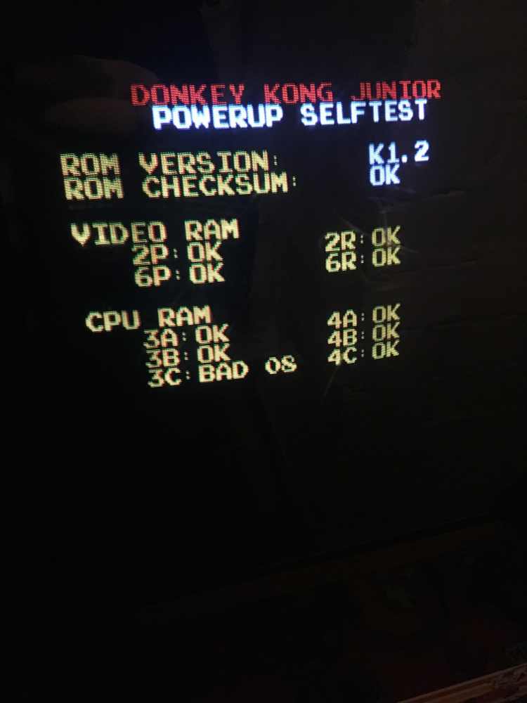
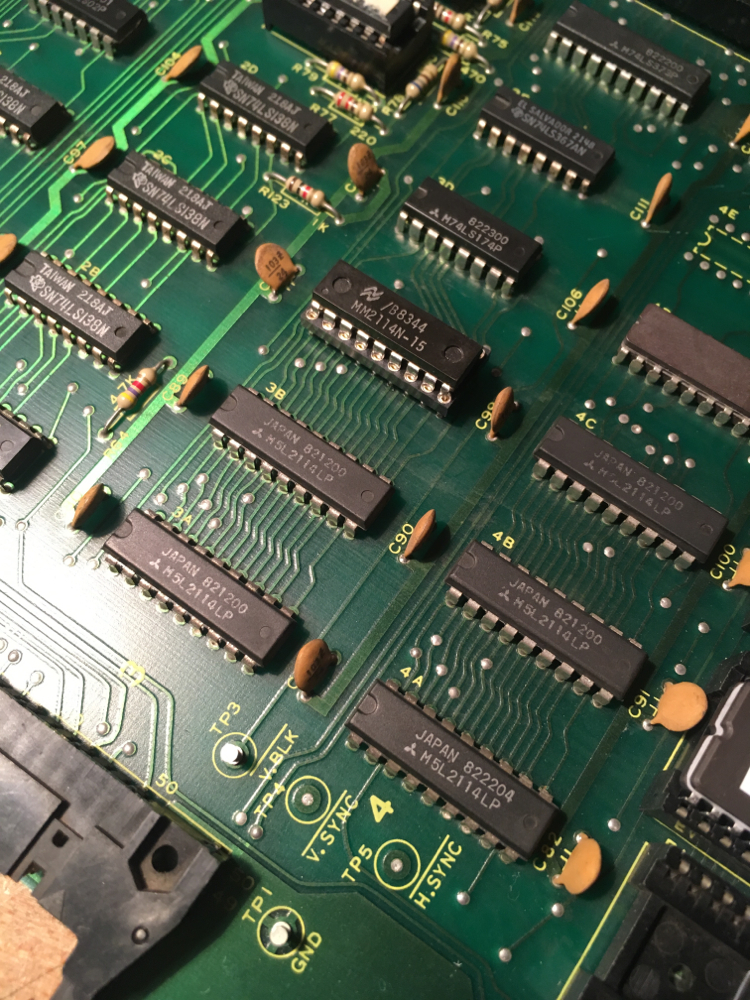
Now here's what is odd, the Chip select signals for the roms are not all pulsing. The one to chip 5B is pulsing but the other 2 are high. Also the select pins for ram chips 3B and 4B are high to. The other 4 rams are pulsing.

As i'm looking at the schematic there is some sort of custom memory address chip at location 4D (3192) which looks like a kind of PAL/GAL type custom logic array, but i can't find any info on this or how to check/replace it.

Does anyone have any thoughts on what this could be and if i'm in the right area with this memory address section, or is there something else that could cause these results?

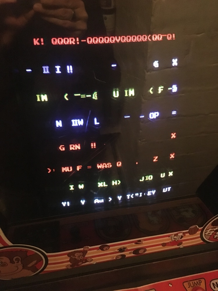
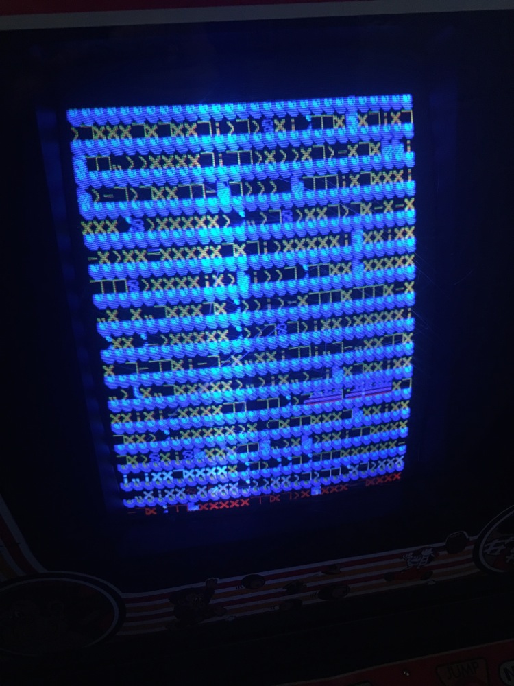
I can't get anything on screen whatsoever, so assume the program is not running.
 

obcd

Active member
Credits
3,830CR
A lot of faults can cause the code to run in a constant loop. If that loop only uses code from one specific rom, the CS of the other rom chips won't pulse low. You could look at the mame code to figure out how the rom's and ram's are mapped into the Z80 address space. Next step could be writing some small Z80 programs that simply jump to an address and have it run in a loop there. You will need one eprom at address zero for the jmp instruction, and one with the loop code.

If you can't burn/erase you own eproms and your cpu is in a socket, than you could statically force an address by removing the cpu and connecting some of the socket upper address lines to 5V and others to GND. At that moment, the corresponding CS line of the address decoder chip should become low. This just tests the address decoder logic.

If you write your own test routines, you have to disable the watchdog or write some code to keep it happy as well.

Other tests could be checking the chips temperature. If some simple logic TTL chips become 2 hot to touch, they are usually bad. Early dynamic ramchips like the 6116 normally become very hot.

If you have a broken pcb trace, you won't find it with this last technique.

I assume you have checked all the roms and eproms on the board? Eproms are only guaranteed to hold their data for something like 10 years. Sometimes they use OTP eproms (without window) as roms.
 

myPinballs

Active member
Feedback
16 (100%)
Credits
685CR
Thanks for the reply.

I should have added that i did a 'hot to touch' test and can't find anything getting hot. The thing that led me to believe the z80 wasn't running correctly first of all before getting the logic probe out was the game roms and z80 weren't warm to touch like they are normally, so that made me think the z80 wasn't working in a normal way.

Game roms are newly burned ones i did and the z80 was replaced just to be sure. No different.

The annoying thing here is the donkey kong jr version of the 2 stack board has different memory addressing logic form the dk version. Dk jr uses 3 2764 game roms and this custom ic that is a magic black box job. Also from reading up on this, the memory addressing is in pages across the 3 roms not sequentially like earlier.

All makes it that bit more confusing to trace through :(

I do know that rom 5B hold address 0 so that makes sense in that this is the one with a pulsing chip select line.

myPinballs2016-10-21 14:14:40
 

myPinballs

Active member
Feedback
16 (100%)
Credits
685CR
Ok i made some progress. If i remove game rom 5C then all rom cs lines pulse and i get a picture, although its garbage it does confirm other things like the clock, colour data and sync is ok.

Still trying to work out if this help identify something on the address map

IMG_7143.jpg


IMG_7145.jpg


Also tried with just rom 5B installed and got this

IMG_7149.jpg


myPinballs2016-10-21 19:50:44
 

obcd

Active member
Credits
3,830CR
Maybe you could test with that rom back in, but it's /CS or /OE tied to VCC instead of connected to the address decoder. (I normally put a 1K resistor between VCC and the chip inputs.)

If the rom chip is ok, you should get the same result as with the chip removed.

If the chip is bad, you will end up without picture again.

As all chip data lines are on the same tri state bus, one chip being bad can corrupt that bus.

If you have a spare eprom chip, you could simply program and try that.

If the chip doesn't become tristate on all data lines, it's possible that it tests ok in the programmer but isn't.
 

myPinballs

Active member
Feedback
16 (100%)
Credits
685CR
Have tried with a new 5C rom using the online files and with the original 5C rom the board came with. Both give the same result. Will double check the checksum of the rom via my dataman programmer and also the socket on the board.
 

myPinballs

Active member
Feedback
16 (100%)
Credits
685CR
Checked everything and had the oscilloscope on all address, data and cs pins. Can't seem to find any 'logic' based issues. I.e a line stuck high or low or floating Was hoping it was just a dead logic chip somewhere.

The only thing i can think is that something is up with a ram chip and that when the program enters an instruction held in rom 5c the data it is trying to write or read from a certain ram location is messing things up. The problem is i'm not sure how to work out which rom address is being accessed when the issue occurs and more importantly which ram address is at fault. I need a fluke 9010a!
 

myPinballs

Active member
Feedback
16 (100%)
Credits
685CR
Also, double checked the clock frequency output. Looking in MAME is states the clock as 3.0659Mhz.

From my Oscilloscope i got 3.077Mhz. Pretty close!

IMG_7152.jpg
 

myPinballs

Active member
Feedback
16 (100%)
Credits
685CR
Anyone know if you can get test roms for these nintendo era boards? I have a braze high score save mod coming that has built in diagnostics, so hoping to use that to help identify my board fault, but was wondering if there are any standalone roms you can plug in to assist with diagnosing ram/i/o/port faults etc.

Pinball cpu boards have lots of diagnostic roms you can use for most generations.
 

myPinballs

Active member
Feedback
16 (100%)
Credits
685CR
Update on my journey to fix a dead donkey Kong Jr PCB. I managed to pick up a braze kit with built in diagnostics and that helped me identify a Bad ram chip 3C as previously thought.

IMG_7268.jpg


This kit with built in diagnostic was exactly what i needed to help identify the fault. Showed that bit3 for the 3rd ram bank was stuck high.

IMG_7266.jpg


Replaced there chip, as is the same type of ram used in various pinball boards to of this era

IMG_7272.jpg


and bingo!

IMG_7274.jpg
IMG_7275.jpg


Majorly chuffed to get the board back from the dead! Now have DK and DKjr i can play in my space firebird upright cab :) Work on my nintendo board switcher pcb now has 2 boards to test with !
 
Top