Help identifying psu component

Hurray Banana

Moderator
Staff member
vacBacker
Feedback
8 (100%)
Credits
2,755CR
Hi working on rebuilding my Sega Rally psu.

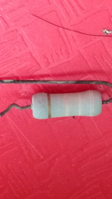
It's got a bit hot and I'm replacing the caps but though I better replace these resistor looking components that have been baked so badly they are unreadable (the legs are black). The ones I can't read are the four light blue items stood in front of the caps.

burnt_components_in_situ.jpg


Here's one desoldered

fried_component.jpg


I tested it assuming it was a resistor and was getting between 900 and 950 ohms

Luckily I've got another psu that's not as burnt up. I read the resistors from the markings as 1K ohm, it read about 1040 ohm on the meter.
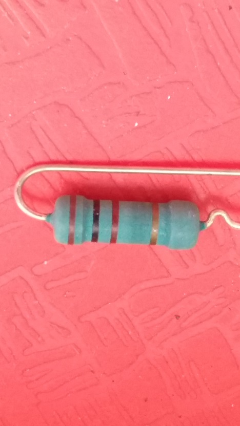
component.jpg


Can someone just double check me as I find telling some of these colours apart incredibly hard. Is there anything special about this resistor (if it is one) like fusable or non flammable?

Cheers

Hurray Banana2016-04-10 14:38:21
 

Battlezone

Active member
Feedback
1 (100%)
Credits
410CR
I can't comment on the resistance value, but as VirtVic says they are

regular high wattage resistors.

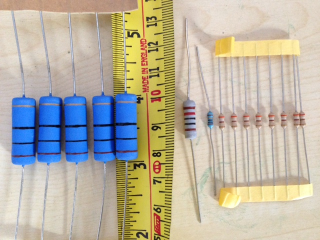
Here are the approximate sizes. 5W for the big ones in this

picture, then 2W, then mostly 1/4W (sometimes 1/2W)

for the regular ones.

Measure the size to get find out which wattage they probably are.

IMG_2061.JPG
 

silverfox0786

Beware the Hillman
Feedback
47 (100%)
Credits
2,699CR
those are metal oxide resistors

also dont go by size any more

todays technology is progressing

i have 1/4W resistors the size of 1/8W and 1W resistors the size of 1/4W

silverfox07862016-04-10 16:48:33
 

Battlezone

Active member
Feedback
1 (100%)
Credits
410CR
If you don't have the schematic or parts list and you want to swap them what do you do in practice?
Try VAPS to see if someone has more info. Personally I'm not even sure I would swap them unless the resistance is off (is that a +/-5% gold tolerance band?)

As Silverfox points out a modern resistor (like the ones in my pic) of the same size as a vintage one should have a similar or better power rating, so I suspect we'd agree that size is probably an ok way to go if you are stuck without the part's real specifications (even though you may run the risk of over engineering it slightly).

Battlezone2016-04-11 02:42:52
 

obcd

Active member
Credits
3,830CR
You could measure the voltage across them to figure out the wattage you need. Just be very carefull as such a supply contains very high dangerous voltages. It wouldn't suprise me if those resistors form a load on one of the supply rails, so that there is always a minimum load.

If they are part of the supply primary switching area, the voltage measurement might be incorrect. In such case, it needs to be done with a scope and the supply needs to be connected to an isolation transformer to isolate it from the mains.

It doesn't harm to put a "higher wattage" resistor, as long as you have the space for it.
 

Hurray Banana

Moderator
Staff member
vacBacker
Feedback
8 (100%)
Credits
2,755CR
obcd said:
You could measure the voltage across them to figure out the wattage you need. Just be very carefull as such a supply contains very high dangerous voltages. It wouldn't suprise me if those resistors form a load on one of the supply rails, so that there is always a minimum load.

If they are part of the supply primary switching area, the voltage measurement might be incorrect. In such case, it needs to be done with a scope and the supply needs to be connected to an isolation transformer to isolate it from the mains.

It doesn't harm to put a "higher wattage" resistor, as long as you have the space for it.

thanks
 
Top