silverfox0786
Beware the Hillman
Hey guys
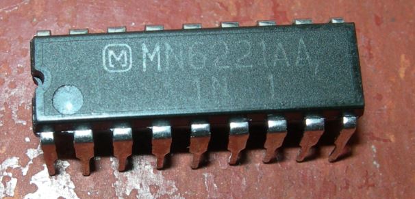
does anyone know what IC49 is on a phoenix
im really strugling to read the manual as its really blurry
thanks
does anyone know what IC49 is on a phoenix
im really strugling to read the manual as its really blurry
thanks
")