Joust screen adjustments?

Judder

Active member
Feedback
2 (100%)
Credits
1,009CR
Amusing myself while I get my Defender boards fixed (thanks!) I've installed the Joust boards I have into the cabinet and they seem to be booting fine.

ROM boards shows 0, and the test 'Advance' buttons in the coin door show what looks like the white test grid and various other things.

The game seems to run too but the problem is is that the picture is very skewed and seems difficult to adjust correctly (see below).

Could this be the monitors fault or is there an easy way to check if the board is wrong, connections are wrong or the monitor is having a bit of a flip-out?

Many thanks!

Joust home attract screen

IMG-20120724-00216.jpg


Joust in play

IMG-20120724-00214.jpg
 

Judder

Active member
Feedback
2 (100%)
Credits
1,009CR
Could it be something to do with the Joust outputting a +SYNC and the Wells Garner monitor I have needing -CSYNC?

"One quick errata before we begin in regards to the Williams manuals:
Code:
Some of them (Stargate and Joust for sure) drawings are incomplete.
	Your interboard wiring drawing probably shows video coming out of a 7
	pin connector (IJ3 "Monitor Control") as follows:
	
	N/C    7
	H Sync 6
	V Sync 5
	GND    4
	Blue   3
	Green  2
	Red    1
	
	If so, it's wrong.  Composite sync is available at the unused pin
	(number 7 cabled "N/C").  It is indicated on the schematic pages but not
	on the wiring harness diagram.  [b]The problem with this sync is that it is
	an active high composite sync so you have to run it through a TTL
	inverter as MAMMA is looking for active low composite sync.[/b]"

Reference:

http://www.mikesarcade.com/cgi-bin/spies.cgi?action=url&type=info&page=Williams-hardware.txt

and

http://www.tomshardware.co.uk/forum/82234-25-sync-issues

Robotron2084 website seems to have the schematics for an inverter

http://www.robotron-2084.co.uk/techwilliams2jamma.html#video

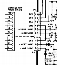
and I've attached the Wells Gardner pin out which shows both + and - VSYNC and HSYNC so any thoughts much appreciated!

Alex
WellsGardnerPinOut.jpg
 

cliff_poole

Active member
vacBacker
Feedback
6 (100%)
Credits
1,069CR
Where do the wires from pins 5, 6 and 7 go to on your monitor ?. Should be able to do it from the colour coding of the wires without the need for a mutimeter.

From the monitor pinout, it doesn't have a Csync input, so I guess you'd have to make sure that +V and +H are wired up to the right places.
 

bbz149

Active member
vacBacker
Feedback
26 (100%)
Credits
1,608CR
When I got my Defender it was sold with a scrolling picture,
but turned out somebody unplugged the video out from the game board but
connected it back leaving the bottom pin unused, when it should be the top pin that
was unused
smiley36.gif
 

Judder

Active member
Feedback
2 (100%)
Credits
1,009CR
Mesmeric_G said:
Where do the wires from pins 5, 6 and 7 go to on your monitor ?. Should be able to do it from the colour coding of the wires without the need for a mutimeter.

From the monitor pinout, it doesn't have a Csync input, so I guess you'd have to make sure that +V and +H are wired up to the right places.

5 and 6 are connected however as the cabinet is a Defender with correct loom, the 7 pin plug has no wire at pin 7 (which is the top most one when you look at the CPU board).

5 and 6 appear to go to 5 and 6 on the monitor which is + VERT SYNC and + HOR SYNC so that seems right too.

The connector that connects to the monitor only has a 6 pin plug on it.

Does that all sound correct?
 

Judder

Active member
Feedback
2 (100%)
Credits
1,009CR
bbz149 said:
When I got my Defender it was sold with a scrolling picture,
but turned out somebody unplugged the video out from the game board but
connected it back leaving the bottom pin unused, when it should be the top pin that
was unused
smiley36.gif

Good suggestion! I've checked and the connector is the right away around (with the locking bit facing inwards) and the top pin is empty so that seem correct too.

Maybe it's just Horizontal Hold and Vertical Hold needing some very very gentle adjustments?!
 

Judder

Active member
Feedback
2 (100%)
Credits
1,009CR
Judder said:
bbz149 said:
When I got my Defender it was sold with a scrolling picture,
but turned out somebody unplugged the video out from the game board but
connected it back leaving the bottom pin unused, when it should be the top pin that
was unused
smiley36.gif

Good suggestion! I've checked and the connector is the right away around (with the locking bit facing inwards) and the top pin is empty so that seem correct too.

Maybe it's just Horizontal Hold and Vertical Hold needing some very very gentle adjustments?!

OK - I just checked all the wires and they are correct (red, green, blue, ground, etc.) and after very very careful turning of the pots we can read the skwiffy text on the screen

It says the ROM board is OK and the game boots fine so I might try a different CPU/Video board just in case that is the issue...

Not sure what else to try out really...
smiley5.gif
 
Top