Let's Fix: Mad Dog II: The Lost Gold - 25 Upright

K1ngarth3r

Active member
Feedback
20 (100%)
Credits
803CR
I'm looking for a little help getting my Mad Dog II all hooked up.

I arrived to me with a replacement HANTAREX Polo 25 monitor (It's the original 15Kz one not the Polo 2) and the chassis was loose outside the cab.

The person I bought it from couldn't figure out how to connect it all together again, so I'm having a stab at it...

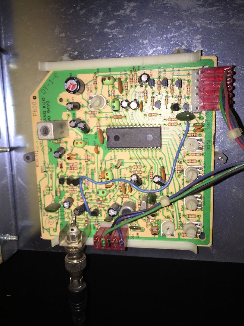
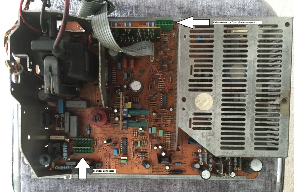
I've read the American Laser Games documentation on these cabinets and can see the GenLock feeding video to the NTSC demodulator board seen below:

Encoder_zpsnfgkacvf.jpg


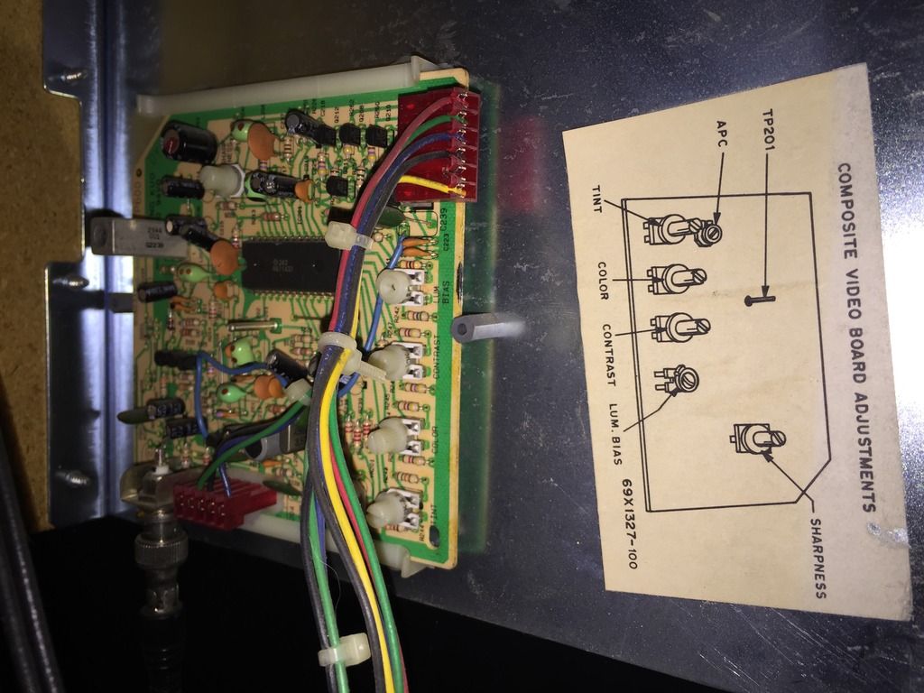
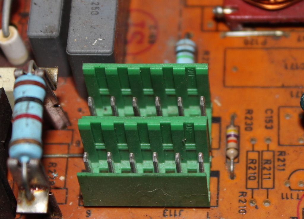
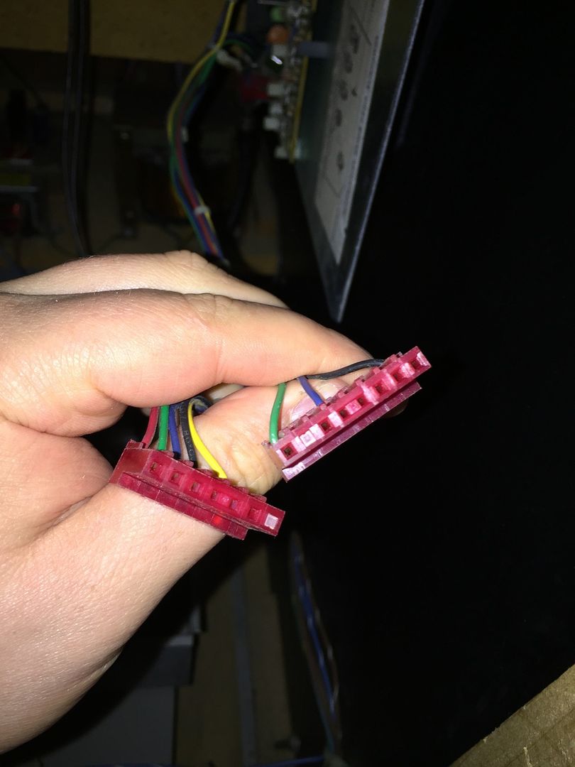
I can see the Laser Disc being fed to it, but there are two red cables (Female) that look like they should hook up to the monitor chassis... I was thinking maybe here:

Board_zpshgc2ikqi.jpg


The problem is, at first glance of the monitors schematics I cannot see what these ports do?

Unfortunately I didn't take pictures of the connectors to count the pins and see if it matches (Will have to pull out again...)

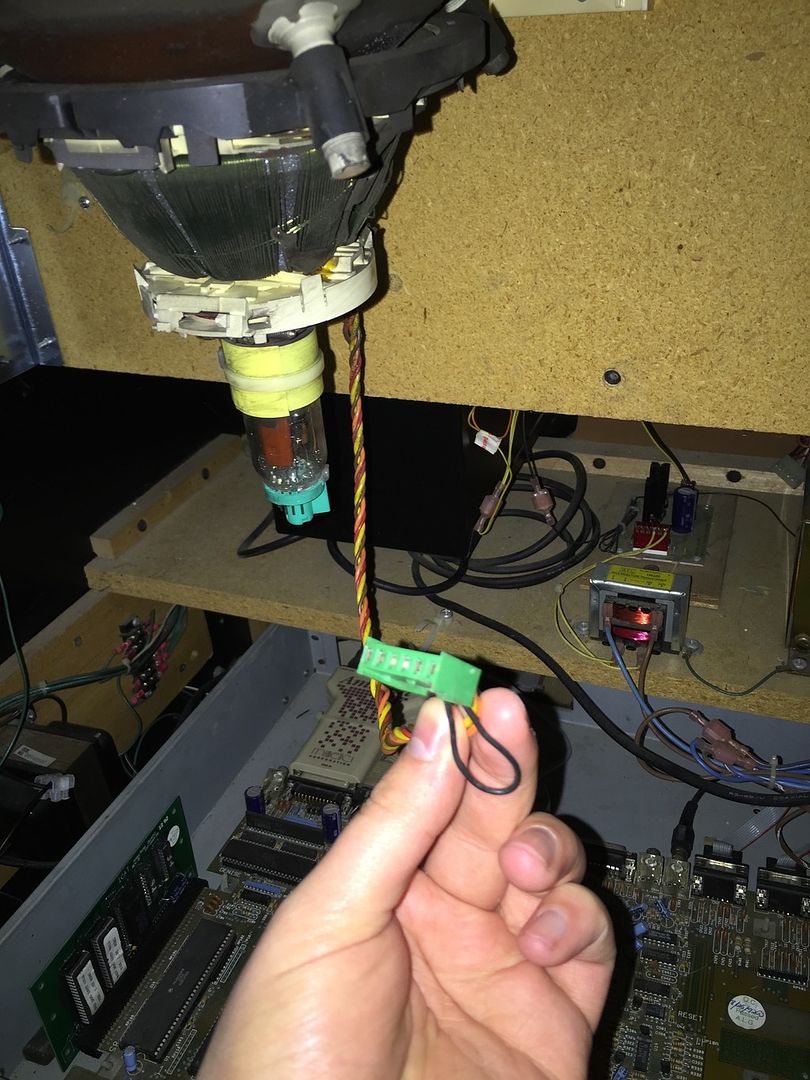
Also there doesn't seem to be a monitor cage to secure the chassis back in place
smiley19.gif


Mount_zpsbadtadva.jpg


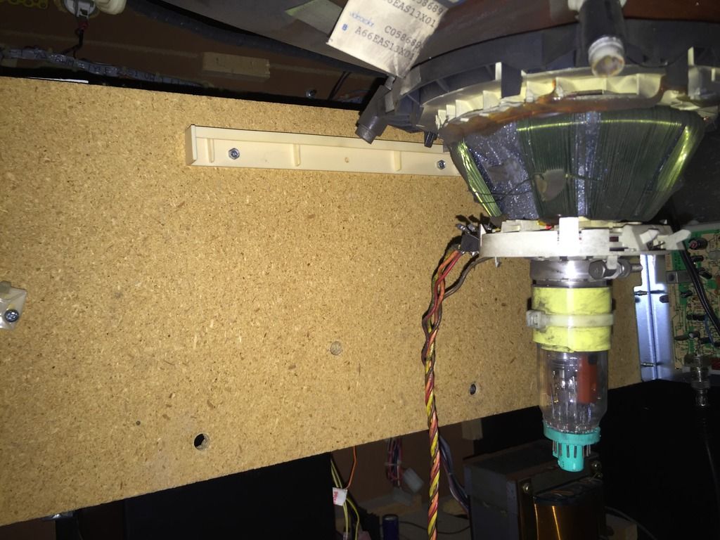
There is a board at the back though, do you guys think it should be secured there?

Thanks all in advanced.

K1ngarth3r2016-12-07 20:57:14
 

obcd

Active member
Credits
3,830CR
Those 2 connectors in the picture are probably for the deflection coil connector. The deflection coil is the one sitting around the neck of the picture tube. There are 2 connectors so you can choose between a normal picture and a mirrored picture. Some older games had a mirror installed on a 45 degrees angle and you where looking at that mirror to the picture tube. So, basically, only one of those 2 connectors is used. There should be a video in connector at the back of the chassis board , next to the power in connector.

On the video connector you have RGB gnd Vsync and Hsync, so that's also 6 pin's.

Don't connect your video signal to one of the deflection coil connectors or you will see magic smoke.
 

K1ngarth3r

Active member
Feedback
20 (100%)
Credits
803CR
obcd said:
Those 2 connectors in the picture are probably for the deflection coil connector. The deflection coil is the one sitting around the neck of the picture tube. There are 2 connectors so you can choose between a normal picture and a mirrored picture. Some older games had a mirror installed on a 45 degrees angle and you where looking at that mirror to the picture tube. So, basically, only one of those 2 connectors is used.

My monitors at 45 degrees angle, not sure which one is which though?

obcd said:
There should be a video in connector at the back of the chassis board , next to the power in connector.
On the video connector you have RGB gnd Vsync and Hsync, so that's also 6 pin's.

I see the video connector next to the power connect on the chassis but there are two cables (6 pins each I think)

obcd said:
Don't connect your video signal to one of the deflection coil connectors or you will see magic smoke.

Haha, of course, I don't have a death wish
smiley2.gif
 

obcd

Active member
Credits
3,830CR
If you have connected your deflection coil to the wrong connector, you will simply see a mirrored image. Power off the system, wait a couple of minutes and plug the deflection coil into the other connector. The one closer to the edge is the normal picture, the inner one the mirrored picture.

You say there are 2 cables that go the monitor chassis. This seem a little strange. A hantarex monitor chassis only has one video connection.

We had a maddog some years ago, but it's monitor was a large panasonic projection tv and I think they used the SCART connector. It started to have problems reading it's laserdisc and my boss finally sold it. I can't remember how the laserdisc video signal and the other electronics video signal are mixed to each other. It might help if you could give more details about the connectors you can't figure out, like where they are going 2 at the other end.
 

K1ngarth3r

Active member
Feedback
20 (100%)
Credits
803CR
Here's a slightly better picture of the video board (NTSC demodulator board)

35239A8C-40CA-41D8-8906-B16C4C1CECF6_zpst6znk30f.jpg


The cables that come off it are here:

83F40708-BC8D-4CFC-8F36-4A066119E321_zpscszq380p.jpg


The one of the left has 6 female connectors and the 7th blocked off so should fit on the chassis... But what about the other... Its a similar configuration but the 2nd hole in is blocked off...

The is the monitor chassis, and there is diagrams on were I think the connectors should go.

1_zpsh6hsavkd.jpg


Monitor Cable

044F4139-F600-4BED-A813-12765F1B5B6E_zpsvnvq277r.jpg


The Deluxe cabinet connect differently to the monitor (using rear projection)
 

obcd

Active member
Credits
3,830CR
The one you call monitor connector is indeed the deflection coil connector, and it's the plug coming from that coil around the crt neckboard that fits in there.

The NTSC demodulator board isn't getting any supply voltages. So, my guess (I repeat, my guess) is that the connector with the black blue and green wire is to provide power to that circuit board. The other one with the RGB, black and yellow wire is the video out that should go to the video connector of your monitor chassis.

Don't forget to connect the ground wire from the tube to the neckboard if you reassemble everything. 2 other connections to the tube are the anode cap and the degaussing coil.

And, like I said before, make sure the monitor chassis is grounded. The middle pin of the power supply connector should be a ground.
 

K1ngarth3r

Active member
Feedback
20 (100%)
Credits
803CR
obcd said:
The NTSC demodulator board isn't getting any supply voltages. So, my guess (I repeat, my guess) is that the connector with the black blue and green wire is to provide power to that circuit board.

But the question is were does that cable connect :S

I can't see any connector were it might go...

Also, I know the chassis can go anywhere, but just wondering were it supposed to go from the factory?

Thanks for all the input so far.K1ngarth3r2015-06-23 15:00:39
 

obcd

Active member
Credits
3,830CR
If it's indeed the NTSC demodulator supply voltage, than it's not going to the monitor chassis board. Can't you figure out from the manual what supply voltages the board needs on which pins? Finding the ground pin shouldn't be that difficult, so just 2 other wires to figure out.

We don't have that machine and it's manuals anymore, and besided that, ours was a deluxe with the huge panasonic rear projection TV. Are you sure those cables are original? The video plug going to the monitor sure isn't what you expect for a hantarex. You say yourself it's a replacement Hantarex. Maybe the original monitor chassis that was in the machine was having a connector to provide power to the NTSC demodulator. If that's the case, you will need an alternative like a small power supply to provide power to the demodulator. Maybe you can feed the signal from the coax to a tv and check if everything else is working. It's just an NTSC composite video signal. If your tv only accepts a pal video signal, you might see a black and white picture.
 

K1ngarth3r

Active member
Feedback
20 (100%)
Credits
803CR
obcd said:
If it's indeed the NTSC demodulator supply voltage, than it's not going to the monitor chassis board. Can't you figure out from the manual what supply voltages the board needs on which pins? Finding the ground pin shouldn't be that difficult, so just 2 other wires to figure out.

I have read the manual but I can't even find reference to the NTSC demodulator
smiley19.gif


obcd said:
Are you sure those cables are original? The video plug going to the monitor sure isn't what you expect for a hantarex. You say yourself it's a replacement Hantarex. Maybe the original monitor chassis that was in the machine was having a connector to provide power to the NTSC demodulator. If that's the case, you will need an alternative like a small power supply to provide power to the demodulator.

No I can't be sure, I've posted on the Dragon's Lair Projects Message Board hoping I can find someone who also owns a 25" upright to validate.

obcd said:
Maybe you can feed the signal from the coax to a tv and check if everything else is working. It's just an NTSC composite video signal. If your tv only accepts a pal video signal, you might see a black and white picture.

That's good idea, I could certainly try that but would have to do it after I move house.
 

Purity

The Oracle
vacBacker
Feedback
17 (100%)
Credits
2,998CR
I've done some research here, and I think I can help :)

That is indeed a NTSC decoder for a Wells Gardner monitor. They came in two flavours - A P371, and a P600, with different voltage to power them. The earlier P371 needs 15v, and the newer revision P600 needs 12v

The pinout is as below:

1-Positive composite sync out
2-Key
3-Gnd
4-Blue
5-Green
6-Red

1-Vcc
2-Vcc
3-Gnd
4-Key
5-Blanking Input

It's also possible to modify this PCB to be used in a Jamma cabinet without modifying the harness or monitor chassis

So your connector looks like it has green - 12v, black - gnd, and blue - blanking input, connected

Hope that helps?

Purity2015-06-23 19:56:06
 

K1ngarth3r

Active member
Feedback
20 (100%)
Credits
803CR
Seems like the RGB from that board can connect to the chassis and then the power connector should connect to another cable fed from the power supply?

Just need to hunt for the cables and see if I can find it (Assuming it's there!)

Any thoughts on mounting the chassis?
 

K1ngarth3r

Active member
Feedback
20 (100%)
Credits
803CR
Okay, so it seems the Wells Gardner monitors have both connectors on the chassis!

I'd assume I need a K7000?

Will need to check the chassis on one of those to see if I can see the connectors...

Anyone have a details picture of the chassis

Are they easy to get hold of?
 

tb2000

Active member
Feedback
4 (100%)
Credits
3,084CR
You've got a P600 demodulator so all you need to do is feed it with a 12v supply on the correct pin. Either get a WG socket for that RGB plug (if you want to keep it as original as possible) and wire a Hanty RGB plug to it, or get a Hanty RGB loom and cut the WG plug off, then connect the RGBHV wires to the corresponding ones on the WG loom. There's no WG K7000 that would've had a 12v out put for that plug (and I doubt very much that ALG got WG to build them a custom monitor!) I would expect that 3 wire plug to connect somewhere down near the pcb set, probably somewhere around the area of the LD player being as it's got a wire for a blanking signal on it - which is what I think you'd be needing for the gun to work - or possibly for the pcb to receive a signal from the gun so it knows where on screen you fired .
smiley1.gif
 

K1ngarth3r

Active member
Feedback
20 (100%)
Credits
803CR
tb2000 said:
You've got a P600 demodulator so all you need to do is feed it with a 12v supply on the correct pin. Either get a WG socket for that RGB plug (if you want to keep it as original as possible) and wire a Hanty RGB plug to it, or get a Hanty RGB loom and cut the WG plug off, then connect the RGBHV wires to the corresponding ones on the WG loom. There's no WG K7000 that would've had a 12v out put for that plug (and I doubt very much that ALG got WG to build them a custom monitor!) I would expect that 3 wire plug to connect somewhere down near the pcb set, probably somewhere around the area of the LD player being as it's got a wire for a blanking signal on it - which is what I think you'd be needing for the gun to work - or possibly for the pcb to receive a signal from the gun so it knows where on screen you fired . 
smiley1.gif

Can you say that again, but this time use big pictures please
smiley36.gif


I got most of it, yeah I saw it was a P600 and that it needs 12v.

I was told that the pin I could use is CN7 but think there must be a cable down were the laser disc is also.

I very much doubt wells Gardner made custom boards for AGL, from what I hear AGL did most things on a tight budget...K1ngarth3r2015-06-23 23:01:40
 
Top