You are using an out of date browser. It may not display this or other websites correctly.
You should upgrade or use an alternative browser.
You should upgrade or use an alternative browser.
Let's Fix: Mad Dog II: The Lost Gold - 25 Upright
- Thread starter K1ngarth3r
- Start date
K1ngarth3r said:tb2000 said:You've got a P600 demodulator so all you need to do is feed it with a 12v supply on the correct pin. Either get a WG socket for that RGB plug (if you want to keep it as original as possible) and wire a Hanty RGB plug to it, or get a Hanty RGB loom and cut the WG plug off, then connect the RGBHV wires to the corresponding ones on the WG loom. There's no WG K7000 that would've had a 12v out put for that plug (and I doubt very much that ALG got WG to build them a custom monitor!) I would expect that 3 wire plug to connect somewhere down near the pcb set, probably somewhere around the area of the LD player being as it's got a wire for a blanking signal on it - which is what I think you'd be needing for the gun to work - or possibly for the pcb to receive a signal from the gun so it knows where on screen you fired .
Can you say that again, but this time use big pictures please
I got most of it, yeah I saw it was a P600 and that it needs 12v.
I was told that the pin I could use is CN7 but think there must be a cable down were the laser disc is also.
I very much doubt wells Gardner made custom boards for AGL, from what I hear AGL did most things on a tight budget...
I think you may need to do that mod shown on that page (wg_ntsc.txt) as I think it outputs a positive sync and the Hanty will need a negative sync. Another odd thing though is that the ALG "Service Manual for all games" says that the Hanty monitors have a "white source" board, which yours doesn't have (unless there's another board hiding somewhere - but then if there was it wouldn't have this WG board). This would probably be instead of that WG board, the manual even says that it's located between the two large pcbs on the chassis. That points to this game maybe using an 25" MTC900/E chassis (fairly rare now i'd think) originally. I believe the white source board is used to make sure that the white flash is of a proper intensity and colour that the gun works correctly. Also a little odd is that the same manual shows the video output coming straight from the genlock and going straight to a video monitor, or even a standard TV. But then they talk about 120v output iso transformer used for the monitor, which points to an arcade monitor being used. I can only assume it came with different monitors/configurations in different countries!

tb20002015-06-23 23:26:19
K1ngarth3r
Active member
Purity said:Was just looking at the schematic on the K7000 Wells Gardner and it does seem to have a +12v on P7 ?
Okay, so would that have had a custom attachment to connect do you think?
I've pm'd Bods to see if he can check in his Mad Dog McCree and shed any light...
K1ngarth3r
Active member
tb2000 said:K1ngarth3r said:tb2000 said:You've got a P600 demodulator so all you need to do is feed it with a 12v supply on the correct pin. Either get a WG socket for that RGB plug (if you want to keep it as original as possible) and wire a Hanty RGB plug to it, or get a Hanty RGB loom and cut the WG plug off, then connect the RGBHV wires to the corresponding ones on the WG loom. There's no WG K7000 that would've had a 12v out put for that plug (and I doubt very much that ALG got WG to build them a custom monitor!) I would expect that 3 wire plug to connect somewhere down near the pcb set, probably somewhere around the area of the LD player being as it's got a wire for a blanking signal on it - which is what I think you'd be needing for the gun to work - or possibly for the pcb to receive a signal from the gun so it knows where on screen you fired .
Can you say that again, but this time use big pictures please
I got most of it, yeah I saw it was a P600 and that it needs 12v.
I was told that the pin I could use is CN7 but think there must be a cable down were the laser disc is also.
I very much doubt wells Gardner made custom boards for AGL, from what I hear AGL did most things on a tight budget...
I think you may need to do that mod shown on that page (wg_ntsc.txt) as I think it outputs a positive sync and the Hanty will need a negative sync. Another odd thing though is that the ALG "Service Manual for all games" says that the Hanty monitors have a "white source" board, which yours doesn't have (unless there's another board hiding somewhere - but then if there was it wouldn't have this WG board). This would probably be instead of that WG board, the manual even says that it's located between the two large pcbs on the chassis. That points to this game maybe using an 25" MTC900/E chassis (fairly rare now i'd think) originally. I believe the white source board is used to make sure that the white flash is of a proper intensity and colour that the gun works correctly. Also a little odd is that the same manual shows the video output coming straight from the genlock and going straight to a video monitor, or even a standard TV. But then they talk about 120v output iso transformer used for the monitor, which points to an arcade monitor being used. I can only assume it came with different monitors/configurations in different countries!
Yep, I've gone over those service manuals and they make no sense, the completely miss out the part about the NTSC decoder! Maybe there for the deluxe models?
I hope I don't have to do the mod, would love to find out what should be there and put it back to factory spec.
So, basically 4 issues.
1. The sync might have the wrong polarity for the hantarex monitor.
2. You will need to find 12V for the NTSC demodulator board.
3. There is a blanking signal on the mystery connector of that board. It might be needed to synchronise the gun.
4. The hantarex might need a white source board to produce a clear flash detected by the gun.
The deluxe wasn't having any special tricks on it's panasonic tv for such. Our Namco Time Crisis II also uses the same gun technique with standard hanty monitors. So, I wouldn't pay much attention on 4 at the moment. (You need a picture first before you can shoot at it to see if you hit something)
Hmm, i've never seen a K7000 (or even a 25K7191, although I haven't seen many!) that has that connector soldered in. That said, maybe ALG got WG to supply them with that soldered in for them? Still not sure about the blanking pin though - i'd have thought it'd be connected to the LD player or pcb, although there is also a "gate" signal on that P7 connector so maybe it uses that?Purity said:Was just looking at the schematic on the K7000 Wells Gardner and it does seem to have a +12v on P7 ?
tb20002015-06-24 00:11:29
That gate signal comes from the LA7823 pin 12. On the chip datasheet it is marked as Horizontal / Vertical sync separation output. Whenever that pulse is present, the RGB input signals seem to be cut off by Q4. Maybe the datasheets of the chip used on that NTSC demodulator board might explain what that signal is needed for. P7 is having the correct number of pin's and the GND, GATE and 12V seem to be on the correct position, but the KEY isn't. On P7, pin 6 is unused so you would expect the KEY on that pin, but on the connector it's on PIN 7. Houston, we have a problem... obcd2015-06-24 09:42:36
K1ngarth3r
Active member
First chance i've had to reply.
But before I do, it seems that someone on the dragon's lair forums say's this
"The Wells Gardner Monitor in my Dragon's Lair is labeled as a 19k4921. It is nothing more than a standard 4900 series monitor chassis with power taps coming off of it for the NTSC card. I spoke with the tech support guy at WG about this at one time, and he says that putting 12vDC into the NTSC card will work just fine. You can tap this off the power supply. The RGB connections are pretty straight forward. You may have to redo the configuration of the wires at the monitor, but it should work fine. You can get the pinouts for the NTSC card in the Tech Centre."
Regards to the Hantarex, do you think it'll be possible to get the 12v working? Maybe Franco could wipe me up a cable to connect to the existing connector that I could just solder on somewhere?
Or will I need to get a Well Gardner?
K1ngarth3r said:First chance i've had to reply.
But before I do, it seems that someone on the dragon's lair forums say's this
"The Wells Gardner Monitor in my Dragon's Lair is labeled as a 19k4921. It is nothing more than a standard 4900 series monitor chassis with power taps coming off of it for the NTSC card. I spoke with the tech support guy at WG about this at one time, and he says that putting 12vDC into the NTSC card will work just fine. You can tap this off the power supply. The RGB connections are pretty straight forward. You may have to redo the configuration of the wires at the monitor, but it should work fine. You can get the pinouts for the NTSC card in the Tech Centre."
Regards to the Hantarex, do you think it'll be possible to get the 12v working? Maybe Franco could wipe me up a cable to connect to the existing connector that I could just solder on somewhere?
Or will I need to get a Well Gardner?
Just wire the 12v from the power supply, as the guy says above. I think you are over complicating this
Purity2015-06-25 19:13:05
K1ngarth3r
Active member
Okay, yeah maybe focusing to much on how it might have been setup to be original as possible.
But wiring 12v from the PSU might be the way to go.
I'll do that I reckon.
Any thoughts on where to mount the chassis, do you think it should go on that back board or should I get a monitor cage?
But wiring 12v from the PSU might be the way to go.
I'll do that I reckon.
Any thoughts on where to mount the chassis, do you think it should go on that back board or should I get a monitor cage?
It should be fine on that back board. The pcb is already mounted on a metal plate, so basically it already has some shielding I have even seen monitor pcb's mounted on a wooden panel without plate. You still have issue 1 and 3 to figure out, but you could try the monitor ignoring them. It shouldn't harm anything.
K1ngarth3r
Active member
I think for now, get everything hooked up and test, that will answer those two points.
I'm probably going to need big pictures on hooking up the 12v from the PSU to the connector.
It might need to wait until I've moved but hopefully I can get started sooner whilst it's fresh in my mind.
I'm probably going to need big pictures on hooking up the 12v from the PSU to the connector.
It might need to wait until I've moved but hopefully I can get started sooner whilst it's fresh in my mind.
K1ngarth3r
Active member
Deleted what was originally here as i've put in more detail below.
K1ngarth3r2016-12-07 21:53:41
K1ngarth3r2016-12-07 21:53:41
K1ngarth3r
Active member
I'm not sure if there is interest in this thread or not but will carry on posting my progress.
I'm planning on replacing the capacitors on the WG K7000 this weekend so hopefully will be ready to put the monitor into my Mad Dog II either over the same weekend or following week.
Today I was looking at double checking all the connections to make sure I know where they're going and also as a refresher as i've not looked at this in sometime.
Here's mock up.
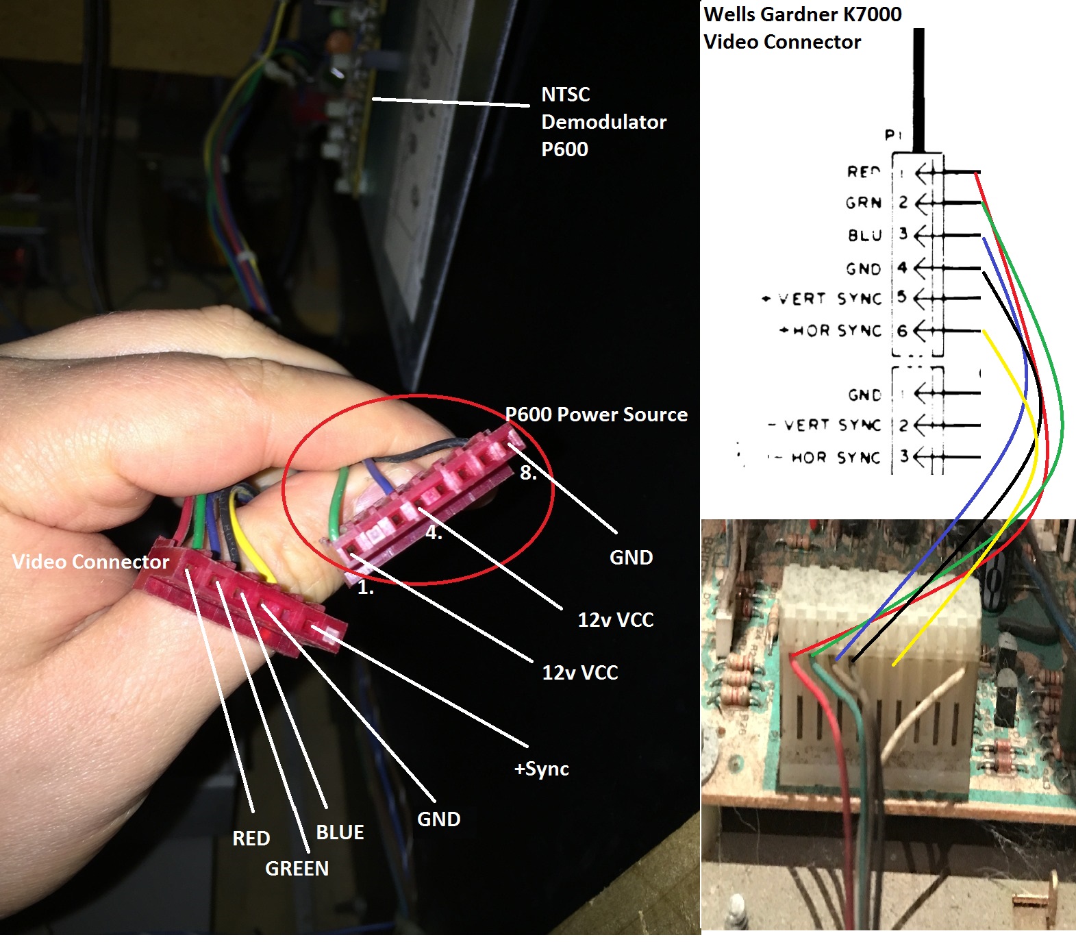
I checked with Franco to see if he could make me a cable but looks like he doesn't do that anymore

I assume I need to order the following to make my own cable to hook up the the power from the P600 NTSC demodulator to the PSU or power source mentioned above on the monitor chassis.
Male PCB Single Row Straight Header Strip
Cable (I can probably use from the existing cable connected to the Video Connector has that's been cut)
Either Spade connector to PSU or Female stackable Header Connector socket
If this is wrong or you have a better suggestion please let me know.
I'm planning on replacing the capacitors on the WG K7000 this weekend so hopefully will be ready to put the monitor into my Mad Dog II either over the same weekend or following week.
Today I was looking at double checking all the connections to make sure I know where they're going and also as a refresher as i've not looked at this in sometime.
Here's mock up.
I checked with Franco to see if he could make me a cable but looks like he doesn't do that anymore
I assume I need to order the following to make my own cable to hook up the the power from the P600 NTSC demodulator to the PSU or power source mentioned above on the monitor chassis.
Male PCB Single Row Straight Header Strip
Cable (I can probably use from the existing cable connected to the Video Connector has that's been cut)
Either Spade connector to PSU or Female stackable Header Connector socket
If this is wrong or you have a better suggestion please let me know.
K1ngarth3r
Active member
Brill! well hopefully i'm close to getting it working (assuming all the other components work okay).
I think I did some poor pictures at my last house but not really at this house.
You can see it in this picture.
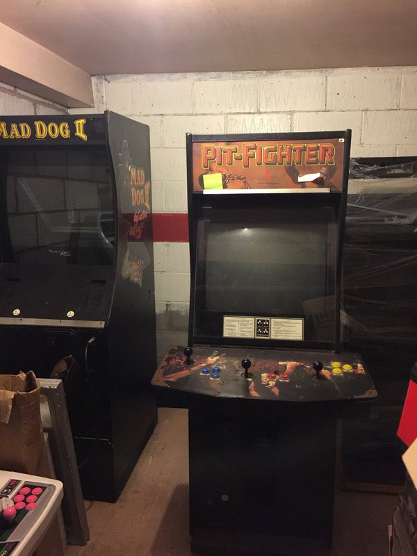
I think I did some poor pictures at my last house but not really at this house.
You can see it in this picture.
K1ngarth3r
Active member
Yeah it's the 25" upright version, it is massive!
The deluxe model comes with a 40 odd" screen (I might be buying one of those...)
K1ngarth3r2016-12-07 22:35:55
The deluxe model comes with a 40 odd" screen (I might be buying one of those...)
K1ngarth3r2016-12-07 22:35:55
I've only just seen this thread, how are you getting on with it? At what stage is the monitor and boards in?
Bear in mind the P600 NTSC card is the same as those in Dragon's Lair 2's. In fact I've bought 2 DL2's that had been converted into ALG's both running Crime Patrol.
It's been a while since I've looked at the back of my DL2 but I think the 12V came from a switcher?
Bear in mind the P600 NTSC card is the same as those in Dragon's Lair 2's. In fact I've bought 2 DL2's that had been converted into ALG's both running Crime Patrol.
It's been a while since I've looked at the back of my DL2 but I think the 12V came from a switcher?
K1ngarth3r
Active member
I'm just about to re cap the monitor and put it in the cab over this week pend and possibly next... ill then try and connect the cables.
If you could take pictures it would really help - I'd love to hook it up as it was originally.
Would also love the DL2 cab!
Did you keep the AGL stuff?
If you could take pictures it would really help - I'd love to hook it up as it was originally.
Would also love the DL2 cab!
Did you keep the AGL stuff?