Missile Command - PCB #2

yorkshire_spam

Active member
vacBacker
Credits
763CR
So I've made a start on fixing my spare Missile Command PCB....

Symptoms: Monitor screams and shuts down (no image visible)

Checks: Verify H-SYNC and V-SYNC

Result: Signals look ok.

For reference here are some healthy traces for each.

HYSNC:


VSYNC:


To my surprise both look fine!

Check: Composite SYNC (Pin 3 LS32@J7 OR position 7 on connector J19):

Result:

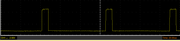
Here's the trace for Composite sync from the PCB (green trace = vsync, yellow trace = csync)
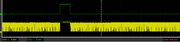


This looks wrong!

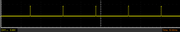
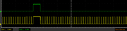
Compare with a healthy c-sync trace:


Check: Verify 74LS32 @ J7

Result: VSYNC input (pin 2) looks fine, HSYNC* input (pin 1) isn't switching cleanly and if floating/high

Check: Verify 74LS74 @ A9

Result: Inputs (pin 2 & 3) are clean, but outputs (pins 5 & 9) are not.

Action: Replace 74LS74 @ A9

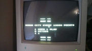
The board will now sync to the screen - will not self test but gives a static yellow screen.

Watchdog is barking.
 

yorkshire_spam

Active member
vacBacker
Credits
763CR
Fault #2:
Symptoms: Board dead, blue/yellow static screen
Check: Clock@CPU

Result: No clock signal

Check: Trace clock signal back from CPU

Result: first IC with valid inputs but not outputs is 74LS74@A7

Action: Replace 74LS74@A7

WD still barking and board will not self test.

Fault #3:

Symptoms: Board dead, blue/yellow static screen
Check: ROM/RAM/BUS using Fluke

Result:

ROMS dead/faulty:

035820.02

035823.02

035824.02

Action: Replace faulty ROMs (borrowed from other PCB as my EPROM programmer isn't working!)

PCB now boots into self test, but clearly still has "issues":


yorkshire_spam

Active member
vacBacker
Credits
763CR
Fault #4:
Symptoms: Graphics in the wrong place, upper half of image AND lower half BOTH on the lower portion of the screen.

Check: Pretty much bloody everything associated with the MADSEL and ram addressing.

I've been round and round in circles on this until I noticed a discrepancy in the schematics. The memory map shows that for all addresses A15 is low. But I noticed that the BA15 feeding the MAD13 line via 74-157@L2 and 74-08@M3


Pin 9 on 74-08@M3 was sitting high, but A15 on the processor was flipping high/low.

So I hooked up the 'scope on pins 2 and 18 of 74-244@F2 (buffer that converts raw A15 to BA15) and the fscking thing started working.

The only possible thing I can think of is that something UNDER F2 wash shorting the output high and hooking the probes up moved it? I ave actually no idea how it started working, I can't actually make it fault now.

Anyway.... COLRAM is still faulty so colours are wrong and blue text is "missing".... onto the next fault!

Edit: I should have checked the MAME driver! It has a different map to the one on the schematics!
http://tech.quarterarcade.com/tech/MAME/src/missile.c.html.aspx?g=1775


yorkshire_spam2018-11-27 17:23:12
 

yorkshire_spam

Active member
vacBacker
Credits
763CR
Double DOH! Missing blue turned out to be a loose connection on the monitor cable!
I'm gonna hook up a trackball and wire up the buttons on the jamma<->missile command adapter to give both PCBs a full test now.

smiley17.gif
 

yorkshire_spam

Active member
vacBacker
Credits
763CR
Update on fault #3:

The board seems unhappy with NEC 2716 eproms to replace the Atari mask ROMs, but is fine with Hitachi ones!

Update on fault #4:
After storing for a while the fault returned, in the end I found a dry joint on pin 2 of the 74--244 @ F2

Re-flowing that seems to have fixed it.
 

yorkshire_spam

Active member
vacBacker
Credits
763CR
The saga continues....
Fault #4 returns!

So I removed the 74ls244 @ F2, socketed that location and replaced it. All seems good for now.

Fault #5:

Symptoms: The scores/highscore are off the top of the screen.

It does this on my test monitor as well as in the cab, so I'm wondering if it's the PCB. I'll try adjusting the monitor in the cab, but I suspect it's to do with the way the addresses are scanned by the screen output

More to follow....

Fault #6:

Symptoms: Trackball will not go UP (left/right and down seem fine though?)

When I have a moment I'll start working through the input circuits.
 

yorkshire_spam

Active member
vacBacker
Credits
763CR
A brief update....
Fault #6 turned out to be the trackball, not the PCB - the original 2.25" TB seems incredibly sensitive to the position of the opto PCB, which isn't nicely fixed as it is on the later plastic bodied ones.

To be safe I replaced the optos on the existing PCBs and then "tuned" the position of the PCBs until I got a good consistent output on both axes.

Investigation of Fault #5 will have to wait as the board has developed Fault #7... it's intermittently running/glitching/resetting. I guess this is what soak testing is for?
 
Top