Missing chip pin tips?

Battlezone

Active member
Feedback
1 (100%)
Credits
410CR
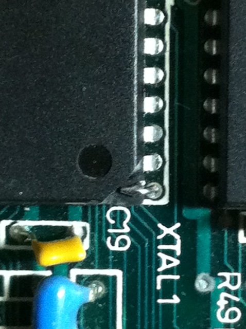
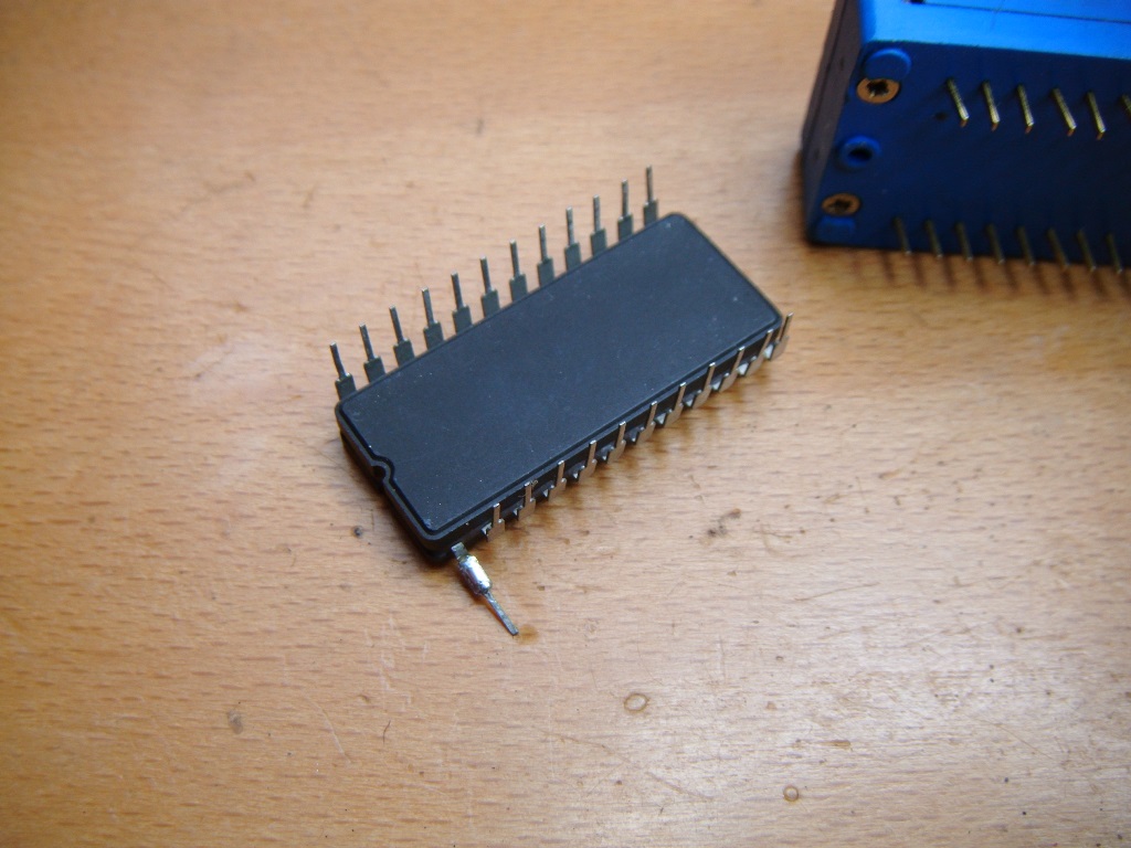
Before I consign this chip to the bin does anyone have
any handy tips on how to reconstruct a pin once it's totally dropped

off?

It's C012294-03 (POKEY) so I'd rather save it if I can.

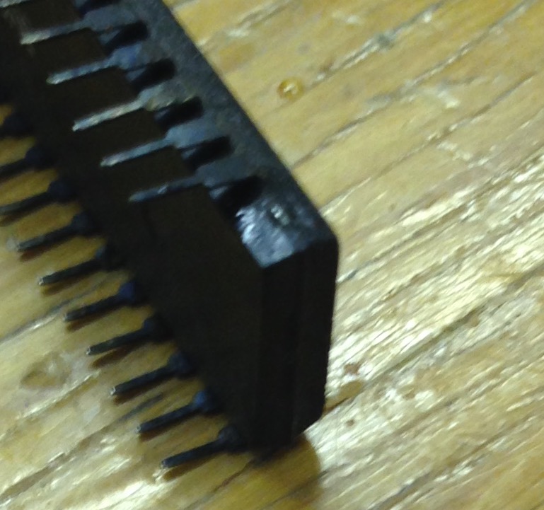
I'm sure we've all had lots of pin failures like this. The small amount of

chip frame showing is totally immune to my solder and

even stripping back the plastic to reveal more metal is tough

(apologies for the blurry photo and pre-cleaned state of the other pins).
chip_pin.jpg


Battlezone2016-04-01 20:42:17
 

Macro

Active member
vacBacker
Feedback
4 (100%)
Credits
1,994CR
you can dremel some plastic away to reveal some more pin to solder to

You used to have to do this on Wii's after they broke the pins off to stop you from chipping them!
 

joe34

Active member
Credits
448CR
hmm no expert here but;
first maybe rough up that small amount of chip frame showing, eg. using a sharp blade to scratch it a little, or something rough..

you might get some solder to stick then

(i think maybe better to solder some wire on there instead of a pin, then would have to run the wire to a point where the pin normally led) not pretty perhaps but still
 

Ace`

PlanB contributor #1
Feedback
40 (100%)
Credits
3,906CR
I'd reveal the missing pin like Macro said using a dremel then clean up the other pins and install it in a socket. Then solder the broken pin directly to the socket using a bit of wire or cap leg. It'll look a little strange when it's installed into another socket having two sockets stacked but it'll also stop any of the other pins getting damaged or falling off.

Also if you need to remove it for any reason you won't have to desolder a jumper wire every time.
 

andrew96

Unfixable? What's that word mean?
Feedback
1 (100%)
Credits
899CR
yep file the corner down to the metal carefully place in a socket and then solder on a wire (or another chip leg if you want) If you solder it into the socket (and a couple of other legs) this gives it mechanical strength and helps stopping more legs breaking off

IMG_5241.JPG


andrew962016-04-01 22:31:08
 

bbz149

Active member
vacBacker
Feedback
26 (100%)
Credits
1,608CR
G, look at the oxidization on the other Pins
smiley3.gif
Most of the Gork Rom boards I have had the same problem! easy enough to solder a leg on with a bit of Flux
 

andrew96

Unfixable? What's that word mean?
Feedback
1 (100%)
Credits
899CR
Fiber pencil helps wonders with the pin oxidization cleaning, just a light going over on the pins is usually enough to clean them up
 

Battlezone

Active member
Feedback
1 (100%)
Credits
410CR
Thanks those are great suggestions guys (macro, joe34, ace, drew96, bbz149).
I'll try filing away and see if I can expose more of the lead frame.

bbz149 - I'm not sure the chip even works, but it seams a pity to bin it

before asking for suggestions.
 

jonhughes

Active member
vacBacker
Feedback
52 (100%)
Credits
1,136CR
I've recently replaced a 28 pin chip off a Namco custom, think it's the 34x one which always corrodes. Every leg gone up to the casing. If they're not up to the casing and some of the pin is still in tact life is much easier. Sand down the pin until shiny and add a drop of solder to the pin. Take a donor chip and using tweesers bend a leg away at the casing. File the back of the donor pin and add a solder plob. Place your chip in a DIL socket. The one with clamp so the legs are on the outside of the socket. This will hold the chip while you solder the donor pin onto the contact. Flux it and solder the pin on.

For legs lost up to the casing My advice is to dremel the casing to reveal the contacts inside the casing. You need to be careful in the final stages of the dremel to avoid perishing the contact. Next, take a needle and scratch the surface of the contact. Apply flux and try to solder a small amount of solder on to the contact. Take your time until each one is done. Once you've done each contact place your chip on the inside of the clamping DIL socket and place the chip in. Do the same thing as above with donor pins. Gently push the donor pin into the socket using tweesers and the needle to align the pin. When it is in the correct position heat the pin and contact so the solder between the two fuses. Add flux and reheat, this creates a better bond. Once all are done take a standard socket and put the repaired chip into it. You will then probably need to replace the socket on the PCB also.

Works for me, if I wasn't in Tenerife I could post pictures of the one I've just done. Will do when I return probably.

Good luck and take your time.
 

jonhughes

Active member
vacBacker
Feedback
52 (100%)
Credits
1,136CR
Forgot to mention, when you are solder the donor pins with part of the contact exposed you can either use the DIL socket to hold the chip and pin steady on the inside of the socket (easier but tricky to align) or use the tweesers to hold the pin while soldering it to the chip on the outside of the DIL socket. When I refer to outside of the socket I mean the row of pins over hang the side of the socket and 'rest' on the external wall casing of the socket.
 

Battlezone

Active member
Feedback
1 (100%)
Credits
410CR
Well I'll be! The chip actually works.

I took the advice, placed it in a socket with robust/round pins,

filed away (by hand), a drop of solder on the two

lead frame contacts and then used single core wire

as the donor pins. Thanks folks.

It's a spare for a rainy day, but that is much better than going

in the bin.

pic1.jpg


FullSizeRender.jpg
 

jonhughes

Active member
vacBacker
Feedback
52 (100%)
Credits
1,136CR
That's a great fix, must have taken a while to hand file. Only possible on the corner legs. I'll post an example when I return from the hols.
 

jonhughes

Active member
vacBacker
Feedback
52 (100%)
Credits
1,136CR
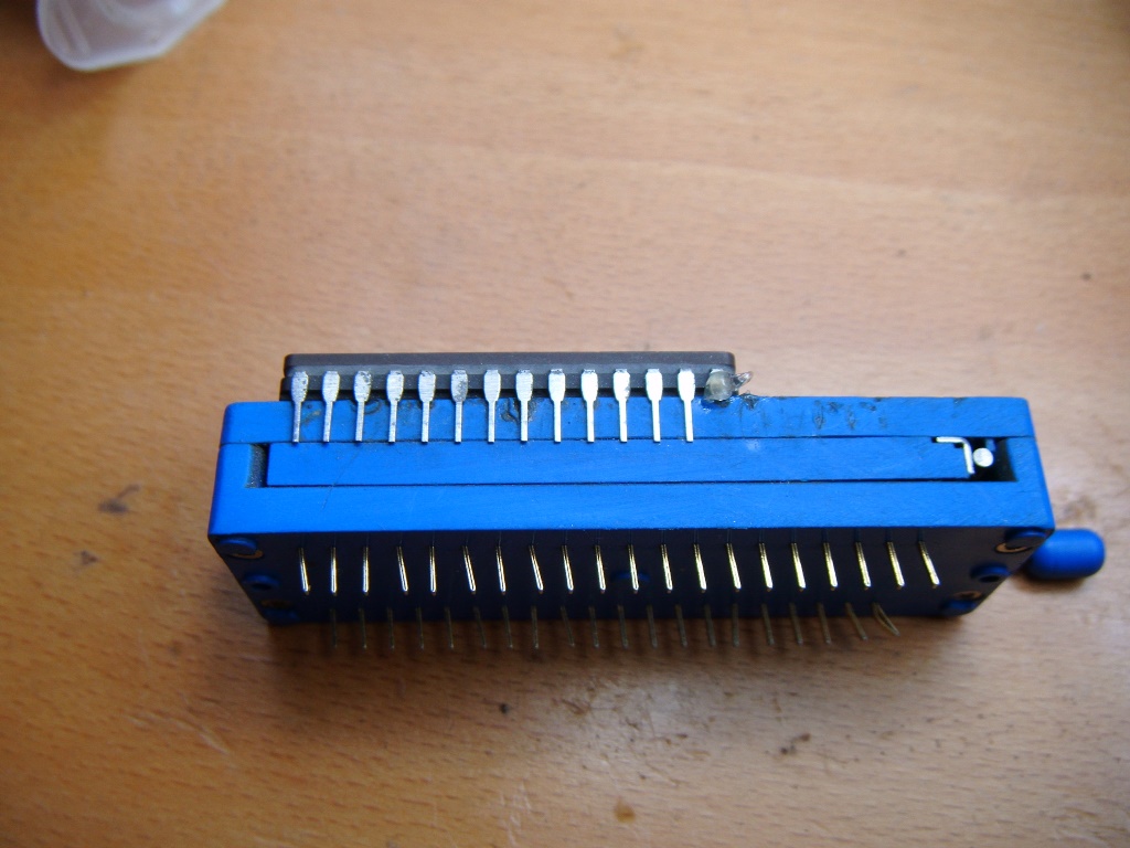
Ok, I needed to repair a chip with a snapped leg. Luckily this one was only the short pin section of the leg, much easier. So, as I said I would, here is the first how to? I'll follow up with the other when I have one to do.

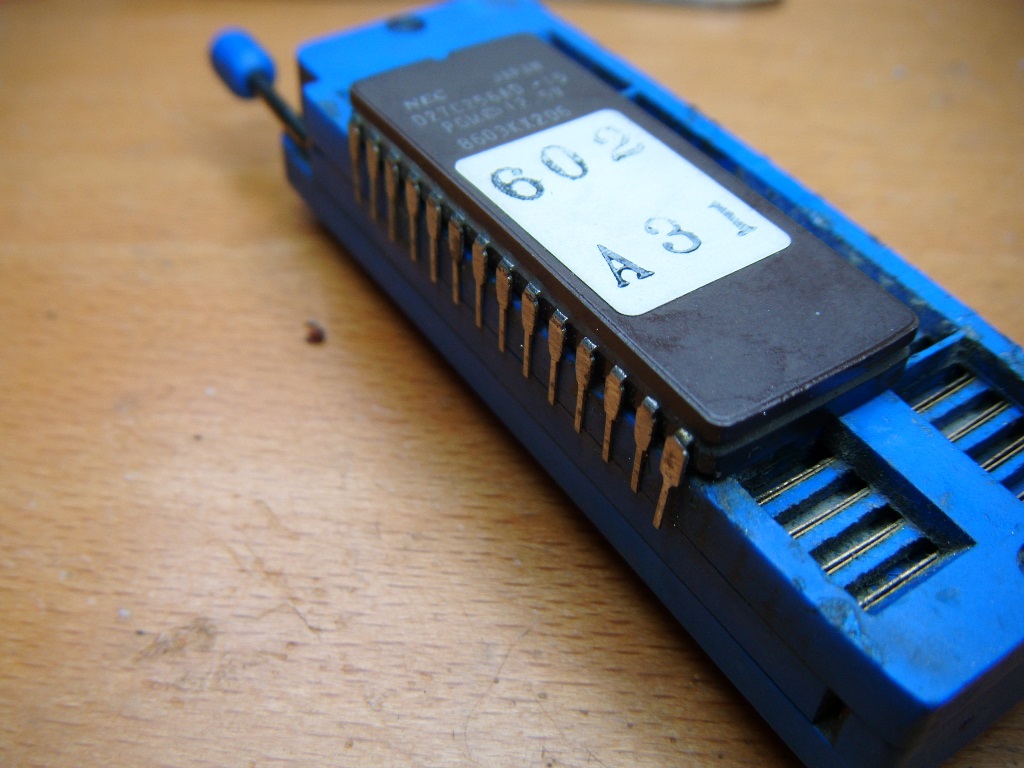
Here is the chip located in the zif socket - this with the legs on the outside of the zif socket, against the casing.

DSCF8035.JPG


The pin has been cleaned and scratched and primed with some flux.

DSCF8036.JPG


Next prime it with solder.

DSCF8037.JPG


Now take a donor chip and scratch the reverse of that pin and prime that with solder.

DSCF8038.JPG


Snip that pin off and, using teasers, carefully solder it on to the broken pin.

DSCF8039.JPG


Use solder mop to remove any excess solder, after having secured the chip on the inside of the zif, so the pin won't move.

It's not perfect but it certainly does the job. I'll write another about when the leg has snapped at the casing and the dremel is required. When I need to do one I'll post similar to this.
 
Top