
You are using an out of date browser. It may not display this or other websites correctly.
You should upgrade or use an alternative browser.
You should upgrade or use an alternative browser.
Model 3 PSU
- Thread starter PhilT
- Start date

Thanks for the advice so far, I am making progress and so had a poke around under the pedal box where the power comes in.
The PSU cord is spliced directly into the 240v line that goes into the transformer so it never gets turned off unless the machine is unplugged. The output from the transformer then goes to the switch on the back of the machine.
The wire that goes to the switch seems very thin to me and there is what looks like burn on the connector block - obviously not stock! There also something that looks like a fuse box of some description that has 2 wires coming out that have been cut flush. Anyone know what this is and how its supposed to be wired?
I am going to take out that 240v PSU splice, but where should the PSU be feed 100v from after the switch?
I put some pics below.
The PSU cord is spliced directly into the 240v line that goes into the transformer so it never gets turned off unless the machine is unplugged. The output from the transformer then goes to the switch on the back of the machine.
The wire that goes to the switch seems very thin to me and there is what looks like burn on the connector block - obviously not stock! There also something that looks like a fuse box of some description that has 2 wires coming out that have been cut flush. Anyone know what this is and how its supposed to be wired?
I am going to take out that 240v PSU splice, but where should the PSU be feed 100v from after the switch?
I put some pics below.
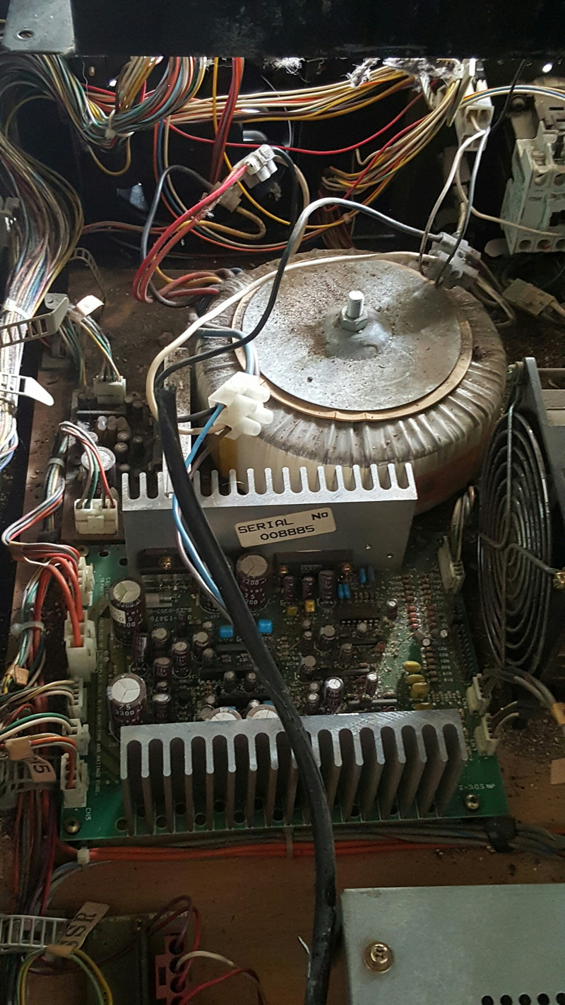
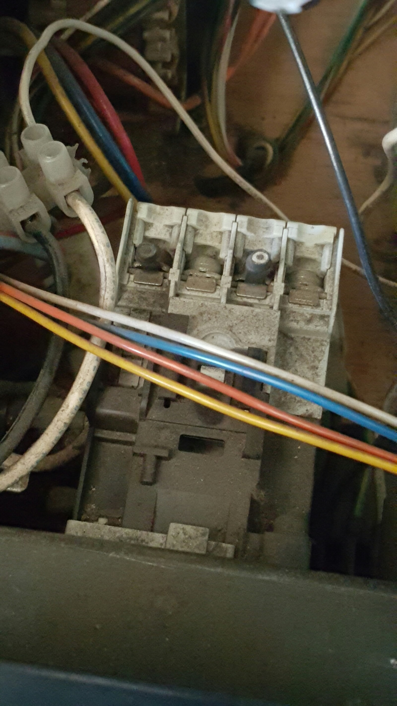


Looks like you've got a Jap cab that's been badly converted to run off 220-240v. The white block thing on the back of the power plate is a contactor which was regs in Japan at the time. That's what makes the crack noise when you power up the cab.
Thanks for identifying it was a contactor. Since found out its a Mitsubishi S-N10.
I am confused as to why someone would bypass the contactor, I am correct in thinking that that means that all current is flowing through the on-off switch rather than the on-off switch being part of a low voltage circuit that should just energises the contactor? Seems dangerous to me.
But then I also found an earth wire screwed into a wooden board...
I am confused as to why someone would bypass the contactor, I am correct in thinking that that means that all current is flowing through the on-off switch rather than the on-off switch being part of a low voltage circuit that should just energises the contactor? Seems dangerous to me.
But then I also found an earth wire screwed into a wooden board...
The idea of the contactor is indeed to limit the current that flows trough the powerswitch. The voltage doesn't need to be lower. It's possible that the contactor coil is a 240V as well.
In our ferrari F355 deluxe, they use contactors to delay the turnon of the monitors. As there are 3 in that cabinet, the startup current would be very high when all 3 are turned on the same time.
That connection on your last picture sure looks like it has overheated. Maybe the screw was fixed on the isolation or became loose. Due to that, the thing heated up and caused the surrounding isolation plastic to melt. This causes the output voltage to fluctuate as well and sure needs your attention.
Normally, you would expect the power switch to activate the contactor, and the contactor should power the main transformer primary and eventually the power supply if you intend to use a 240V type. If you use a 120V supply, it should get it's power from that transformer as well. You might find an original cabinet wiring diagram in the manual.
In our ferrari F355 deluxe, they use contactors to delay the turnon of the monitors. As there are 3 in that cabinet, the startup current would be very high when all 3 are turned on the same time.
That connection on your last picture sure looks like it has overheated. Maybe the screw was fixed on the isolation or became loose. Due to that, the thing heated up and caused the surrounding isolation plastic to melt. This causes the output voltage to fluctuate as well and sure needs your attention.
Normally, you would expect the power switch to activate the contactor, and the contactor should power the main transformer primary and eventually the power supply if you intend to use a 240V type. If you use a 120V supply, it should get it's power from that transformer as well. You might find an original cabinet wiring diagram in the manual.
thanks, I have hunted around for a wiring diagram but the ones i got hold of did not seem to have much detail or are very clear.
http://ohwow-arcade.com/Assets/Game_Manuals/DAYTONA%20USA%202PL.PDF page 100.
Think i will re-instate the contactors and run the power supply off a 110v supply that comes out somewhere after the contactor. At least then I can switch everything off at the power switch, unlike now.
http://ohwow-arcade.com/Assets/Game_Manuals/DAYTONA%20USA%202PL.PDF page 100.
Think i will re-instate the contactors and run the power supply off a 110v supply that comes out somewhere after the contactor. At least then I can switch everything off at the power switch, unlike now.
She Lives again! well one half anyway. Wired the contactor back in and reworked the wiring so its what I think is fairly standard; no more burnt connectors or running the whole current through the on-off switch.
The new psu is powered from a 100v line which I am fairly sure was the supply line to the original power pack. Just got to replicate everything on the right-hand side now.
Thanks for all your help.
The new psu is powered from a 100v line which I am fairly sure was the supply line to the original power pack. Just got to replicate everything on the right-hand side now.
Thanks for all your help.